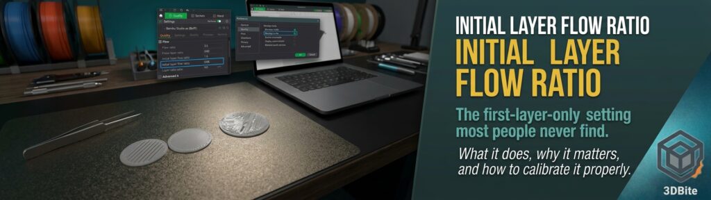
Almost everything on this site about the first layer comes back to the same few levers: a clean plate, the right plate selected in the slicer, a correct Z offset, and sensible temperatures. The first layer troubleshooting post and the elephant’s foot post cover those in depth. There is one more lever that sits quietly in Bambu Studio and does something none of the others do, which is to change how much plastic the printer extrudes on the first layer and on nothing else. It is called the initial layer flow ratio, and once you understand what it is for, it explains a lot of first-layer problems that Z offset alone never quite fixes.
What it actually is
The initial layer flow ratio is a multiplier applied to the extrusion rate for the first layer only. A value of 1.0 means “extrude exactly what the slicer calculated”. A value of 0.95 means 95% of that amount, and 1.02 means 2% more. Every layer above the first is untouched, so the setting lets you tune the foundation of the print without disturbing the flow calibration you have already done for the rest of it.
That separation is the whole point. The ordinary filament flow ratio, covered in the calibration routine post, is tuned against the body of a print, and the MakerWorld calibration models built around this setting note that automatic flow calibration averages across the whole print rather than focusing on any individual layer. The first layer is a special case, so a value that is perfect for layer fifty can be slightly wrong for layer one.
Why the first layer needs its own flow value
The first layer is not printed the way every other layer is. Each later layer is deposited onto soft plastic of a known, consistent thickness, so the slicer’s model of the extrusion, a rounded line of a certain width and height, matches reality closely. The first layer is deposited onto a bare plate, with the nozzle pressed down towards it at a height set by your Z offset, so the plastic is squashed flat and wide by whatever gap the nozzle happens to leave. The plate surface also changes how that squashed line behaves: smooth PEI, textured PEI, and Bambu’s Cool Plate SuperTack all grip and spread plastic differently, as the bed adhesion post explains.
So the first layer’s real behaviour depends on a combination the slicer cannot know: your actual nozzle gap, your plate, and your filament. The flow ratio is the one number that lets you correct for that combination directly. Too much plastic and the lines bulge and ridge, the surface looks rough or shiny, and the excess can squeeze outward into elephant’s foot. Too little and the lines do not fuse, leaving visible gaps and a weak, patchy base. In both cases the print can look fine from the second layer upward, which is exactly why this one is easy to overlook.
Why it is worth the effort
For prints where the bottom is hidden, a slightly imperfect first layer costs you nothing. It matters in four situations.
First, any print where the underside is visible. Display pieces, logo plates, lithophane frames, and anything printed upside down to avoid supports all show the first layer as a finished surface. One MakerWorld calibration model was built specifically because its author kept inverting models to reduce support and found the bottom face unacceptable.
Second, adhesion. A first layer with gaps between lines has less contact area with the plate and is more likely to lift or peel, particularly on larger flat parts.
Third, a new or different plate. The clearest examples in the community involve Bambu’s Cool Plate SuperTack, where first layers were reported as uneven and wavy until the initial layer flow was adjusted, and smooth PEI, where a small increase helped. Each new plate is effectively a new calibration.
Fourth, it saves you from distorting your global flow. Without a first-layer-only control, the only way to fix a bad base is to change the filament flow ratio, which then makes every other layer slightly wrong to compensate.
Where to find it
In Bambu Studio the setting is hidden by default. Open Preferences, scroll to the bottom, and tick Develop mode. The setting then appears in the Process settings under the Quality tab, labelled “Initial layer flow ratio”. It is easy to miss, and some older forum threads wrongly claim Bambu Studio has no first-layer flow control at all, so if you find a thread saying that, it is out of date.
In OrcaSlicer the equivalent control has a different name. It is “Bottom surface flow ratio”, found under Quality with the Advanced view enabled, and the community describes the resulting first-layer flow as that value multiplied by the filament flow ratio. For example, a bottom surface ratio of 0.81 on a filament flow ratio of 0.98 gives a first-layer flow of about 0.79 of the slicer’s calculated amount. Check what your own version of each slicer calls it, because names and menu layouts change between releases.
Before you calibrate: rule out the things it cannot fix
This setting is a fine-tuning tool, and the calibration models themselves say so plainly: it does not replace Z offset adjustment or bed levelling. Running it on top of an unresolved basic problem just masks the problem and gives you a number that is only correct for that specific broken state. Work through this short list first.
- Clean the plate properly and confirm the plate type selected in the slicer matches the plate on the printer.
- Let the printer’s automatic first layer calibration run, and check the Z offset gives a sensible gap. On the A1, the Bambu wiki has a dedicated article on first layer problems where the first layer is too low, and community reports also point to re-tightening the hotend screws.
- Make sure the filament is dry, as covered in the drying post, since moisture produces rough lines that look like a flow problem.
- Calibrate the main filament flow ratio first. The MakerWorld calibration models explicitly assume your filament is already calibrated, so that the first-layer value is a refinement on top of a correct base.
How to calibrate it
The method everyone uses is a test print that lays down several small first-layer patches, each at a different flow ratio, so you can compare them side by side on one plate and choose the best.
Several of these test models exist on MakerWorld, and they work in slightly different ways. One prints a set of circular pads, each corresponding to a different initial layer flow ratio, and tells you to judge by the centre of each circle and ignore the edges, because the edges behave differently from the middle. Another prints a grid of squares, each at a different ratio, and a third uses two-colour filament so the gaps between lines show up clearly. Pick one, load it, print it on the exact plate, nozzle, and filament you intend to use, and note which pad looks best.
Judging the pads is the skill. A good first layer shows smooth, continuous lines that have merged into one surface with no visible channels between them and no raised ridges. If you can trace individual lines with a fingernail, the pad is under-extruded. If it looks glossy, rippled, or has a rough, “cat’s tongue” texture, it is over-extruded. Choose the pad in between, enter that value in the Initial layer flow ratio field, and print a first-layer test with your normal profile to confirm.
Two practical cautions. The value is specific to the combination of plate, nozzle size, and filament, so a different setup needs its own number. And because it is a process setting, it applies to the project you have open. One forum user complained of having to set it for every project and sometimes forgetting, so it is worth saving your result inside a named process preset for that plate and filament rather than relying on memory.
What people have actually found, and why not to copy it
| Reported setup | Value reported | Direction |
|---|---|---|
| Bambu PLA Basic, MakerWorld test author, smooth PEI and similar | 0.95 | Lower, after finding that increasing flow made it worse |
| Bambu PLA Basic on Cool Plate SuperTack, one forum user | 0.8 to 0.94 range tried, settling toward the upper end with a bed temperature tweak | Lower, then partly back up |
| Smooth plates, another forum user | 1.02 | Slightly higher |
| PETG on SuperTack, one forum user | 1.0, left at default | No change needed |
The lesson in that table is that there is no universal number, and the direction is not even consistent. Some setups needed less flow, one needed slightly more, and one needed nothing. One author reported the surprise directly: the first layer looked under-extruded, support suggested more flow, and more flow made it worse, while less flow produced a clear improvement. That is a good example of why you calibrate rather than copy, and why you should treat these values as examples of the range people land in, not as settings to enter.
Reading the symptom
| What the first layer looks like | Likely meaning | First thing to try |
|---|---|---|
| Visible gaps or channels between lines, patchy surface | Under-extrusion on the first layer, or nozzle slightly too high | Check Z offset first, then try a small increase in the ratio |
| Rough, rippled, glossy, or “cat’s tongue” texture | Over-extrusion or nozzle too close | Check Z offset first, then try a small decrease in the ratio |
| Base flares outward at the bottom edge | Excess squish and heat, see the elephant’s foot post | Lower ratio slightly, plus compensation and bed temperature steps from that post |
| First layer is very thin and rough on a new plate or nozzle | Z gap too small; flow may be compensating for it | Fix the Z gap properly rather than relying on flow |
| Perfect first layer, but gaps appear on later layers | Not a first-layer problem | See the over and under extrusion post |
A community workaround worth knowing about, with a caveat
One thread on the A1’s low first layer describes a workaround for a nozzle that sits too close to the plate: raise the initial layer height by the amount the real layer is too thin, then reduce the initial layer flow ratio to match. If the real first layer is 0.07mm instead of the intended 0.1mm, setting the initial layer height to 0.13mm and the flow ratio to roughly 0.77 (0.1 divided by 0.13) restores the right thickness and the right amount of plastic. It is a clever piece of reasoning, and it is worth understanding as an illustration of how the two settings relate. It is still a patch over a hardware problem, though, and the better long-term fix is to correct the Z gap itself.
The practical summary
The initial layer flow ratio is a small setting that does one precise job: it lets you tune the first layer’s extrusion independently of everything above it. It matters most for visible bottom surfaces, for new or unfamiliar plates, and for anyone chasing a consistently good base without compromising the rest of the print. Enable Develop mode, fix the basics first, print one of the pad-style calibration tests on your actual plate and filament, choose the best pad, and save the result in a named profile. If your first layers are already clean, you do not need to touch it, but for the plate or filament that never quite looks right, it is the setting that most often closes the gap.