The general orientation post on this site covered why orientation matters across strength, surface finish, and print reliability all at once. This one narrows in on a single, specific, extremely common frustration: a functional part — a hook, a bracket, a clip — that looks fine, feels solid in the hand, and then snaps clean in half the first time it is actually loaded. That failure has a name, a specific cause, and a specific fix, and understanding it properly with real numbers and real examples is worth a dedicated post rather than a paragraph inside a broader one.
The number that explains almost every snapped part
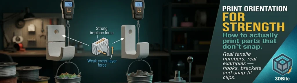
An FDM print is not a solid block of plastic. It is thousands of extruded lines, partially welded together. Within a single layer, the plastic is continuous and genuinely strong — the same molecule-level bonding you would get from injection-moulded plastic. Between layers, all you have is the weld: two surfaces that briefly melted against each other and fused, imperfectly, before the next layer went down. That difference is not marginal. One documented test on a Bambu A1 Mini running standard PLA Basic at 220°C with stock cooling measured tensile strength at roughly 48 MPa when pulled along the extrusion direction (within a layer) versus roughly 28 MPa when pulled across layers (the Z direction) — a genuine 40-60% strength penalty depending on material, temperature, and cooling, just from asking the same plastic to resist force in the wrong direction. Almost every broken hook, snapped bracket, and cracked clip fails the exact same way: cleanly, along one flat layer plane, because that plane is where the actual weakness lives.
Reading a broken part to diagnose what actually went wrong
Before changing anything, look at the actual break. It tells you which of two different problems you have, and they need different fixes. A clean snap exactly along the layer lines — a flat, almost machined-looking break face — means the material itself was fine but the interlayer bond failed. This is an orientation problem, and it is the one this whole post is about. A part that shattered into several irregular pieces rather than breaking along one clean plane means the material itself was too brittle for the load, regardless of orientation — standard PLA under a genuine impact is the classic case, and the fix there is a tougher material rather than a rotation. A part that visibly stretched and deformed before finally breaking means the layer bonding was actually good; it simply was not rigid enough for the application, which is a stiffness problem rather than a strength-orientation one. Only the first of these three — the clean, flat snap along layer lines — is what orientation actually fixes.
Worked example 1: the hook
A wall hook is the textbook case and worth working through in full because the logic transfers directly to almost every other hanging or pulling application. If a hook is printed lying flat, on its side, the layers stack horizontally through the hook’s curve — which means the pulling force, straight down under the weight of whatever is hanging on it, runs directly across those horizontal layer lines. The hook is now relying entirely on the weak interlayer weld to resist the load, and it will fail at a fraction of what the plastic itself could handle. Printed standing upright instead, with the layers stacked vertically through the hook’s height, that same downward pulling force now runs along the layer lines rather than across them — the load is carried by continuous, fused plastic rather than by the weld between two separate layers, and the same hook, same plastic, same print settings, holds dramatically more weight simply because of a 90-degree rotation before slicing.
Worked example 2: the wall bracket
This is described consistently across multiple sources as the single failure seen most often on real functional FDM parts, and it is worth naming exactly why. A bracket mounted flat against a wall, printed with its layers running horizontally (the orientation that minimises support material and looks like the obvious choice in the slicer), takes a downward load from whatever is resting on it — and that downward force peels the horizontal layers apart at the interlayer bond rather than stressing the bulk of the material. The part fails at a fraction of its actual potential strength, not because the design was wrong, but because the orientation put the load exactly where the print is weakest. Rotating the same bracket so its layers run vertically, or angling it so the primary load compresses the layers together rather than peeling them apart, changes the outcome completely — the identical CAD file, printed in a different orientation, survives a load that would have snapped the flat version immediately.
Worked example 3: the snap-fit clip
Snap-fit clips deserve their own example because the failure mode is slightly different from a hook or bracket — the arm has to flex repeatedly rather than just hold a static load, and the root of the arm, where it meets the main body, is where nearly every snap-fit clip eventually cracks. The most reliable orientation prints the arm so it flexes within its own layer plane rather than across it — meaning the layers run along the length of the arm, in the direction it actually bends, rather than stacked perpendicular to that bending motion. The single most common snap-fit failure, described consistently across every design guide researched for this post, is a clip that cracks at the root on first flex, and it is almost always either the wrong orientation, a missing fillet at the root, or both. A fillet at the root — even a modest 1-2mm radius — spreads that repeated flexing stress over a larger area rather than concentrating it at one sharp internal corner, which is exactly the kind of stress-concentration point that initiates a crack. Combine the correct orientation with a root fillet and a tougher material like PETG rather than standard PLA, and a clip that used to crack on the first or second use will survive hundreds of engagement cycles.
Worked example 4: the annular ring, where the rule genuinely changes with scale
This is a genuinely useful nuance that most orientation guides skip, and it is worth knowing because it is one of the few cases where the “obvious” orientation choice actually depends on the part’s size rather than a fixed rule. For a small snap-fit ring — a lens retainer, a cap, anything under roughly 30mm in diameter — printing it flat, so the extruded bead runs parallel to the build plate around the ring’s circumference, is the stronger choice. The ring stretches in-plane during assembly, which stresses the material along the extrusion direction rather than across a stack of layers. Above roughly 30mm diameter, that same ring typically has enough circumferential length that strain distributes across many perimeter lines even when printed upright, and the vertical orientation — which also gives a cleaner cylindrical form and avoids needing support on the interior — becomes the more practical choice without meaningfully sacrificing strength. There is no single universal answer for “how do I print a ring” — it genuinely depends on the diameter.
The one case where you deliberately want the weak orientation
This is a genuinely interesting exception worth including, because it demonstrates that understanding the mechanism matters more than blindly following “always orient for strength” as a rule. A published engineering paper on a breakaway utensil attachment for robot-assisted feeding — a safety mechanism designed to snap cleanly if it collides with something during use, rather than transmitting force to the person being fed — initially oriented the part with layer lines perpendicular to the intended break line, maximising strength in the way this whole post has been describing. The result was inconsistent, unpredictable breaks, which is exactly the wrong behaviour for a safety-critical breakaway component. The fix was to deliberately reverse the orientation, aligning the layer lines parallel to the intended break line specifically to exploit the interlayer weakness this post has spent the whole time explaining how to avoid — producing a clean, predictable, low-injury-risk break exactly where the design intended it. The lesson: orientation-for-strength and orientation-for-controlled-weakness are the same physics pointed in opposite directions, and knowing which one your specific part actually needs is the real skill, not a fixed rule to apply everywhere.
Beyond orientation: the geometry fixes that compound the effect
Orientation is the highest-leverage single decision, but it is not the only one, and the fixes below stack with correct orientation rather than replacing it. Sharp internal corners are stress concentrators — a crack initiates at the sharpest point of an internal corner and propagates from there, which is exactly the mechanism behind most snap-fit root failures described above. A fillet (a rounded internal corner) spreads that same stress over a larger area and dramatically reduces the chance of a crack ever starting; even a 1-2mm radius makes a measurable, real difference. Wall thickness matters specifically at hook and clip contact points — 3-4 wall lines, or a wall thickness of roughly three times the nozzle diameter, is the commonly recommended minimum for any flexing snap-fit arm, since thin walls at exactly the point of highest repeated stress are a direct invitation to crack there first. And for anything genuinely load-bearing and permanent, embedding a heat-set brass insert at the fastening point, as covered in the heat-set inserts post, moves the fastening stress away from a plastic thread entirely — worth doing at the mounting points of a bracket even after orientation and fillets have already been sorted properly.
Testing it properly rather than guessing
A genuinely useful, repeatable home test for anything hook-shaped: print a standard carabiner or hook STL from a community model site, secure the top to a fixed overhead anchor, attach a digital luggage scale to the bottom, and pull down slowly — either by hand or by hanging a bucket and adding water gradually — recording the exact weight shown on the scale the moment it snaps. Print the same file in two different orientations and the result makes the whole argument in this post concrete rather than theoretical. For a quick shock-resistance check rather than a slow pull, a simple drop test works the same way: a standardised 20mm test cube, a fixed drop height, and a consistent weight dropped onto it, comparing orientations and materials side by side. Neither test requires anything beyond parts already in most workshops, and both turn “orientation matters” from an abstract claim into a number you have actually measured on your own printer.
The quick reference
| Part type | Weak orientation | Strong orientation | Extra fix worth adding |
|---|---|---|---|
| Hanging hook | Lying flat, layers horizontal through the curve | Standing upright, layers vertical along the pull direction | Thicker wall at the load-bearing curve |
| Wall bracket | Flat against the wall, layers horizontal | Rotated so layers run vertically or at an angle that compresses rather than peels | Fillet at the mounting-to-arm junction |
| Snap-fit clip | Layers stacked across the flex direction | Layers running along the arm’s length, in the flex plane | Root fillet, PETG instead of standard PLA |
| Small ring (under 30mm) | Printed upright, stretch force crosses layers | Printed flat, stretch force runs along the bead | Slight wall thickness increase if repeated flexing is expected |
| Large ring (over 30mm) | N/A — vertical is generally fine at this scale | Vertical, for cleaner form and no internal support | None specific — strain distributes across enough perimeter length |
| Intentional breakaway part | N/A — this is the goal | Layers parallel to the intended break line (deliberately weak across that plane) | Controlled wall thickness to tune the exact breaking force |