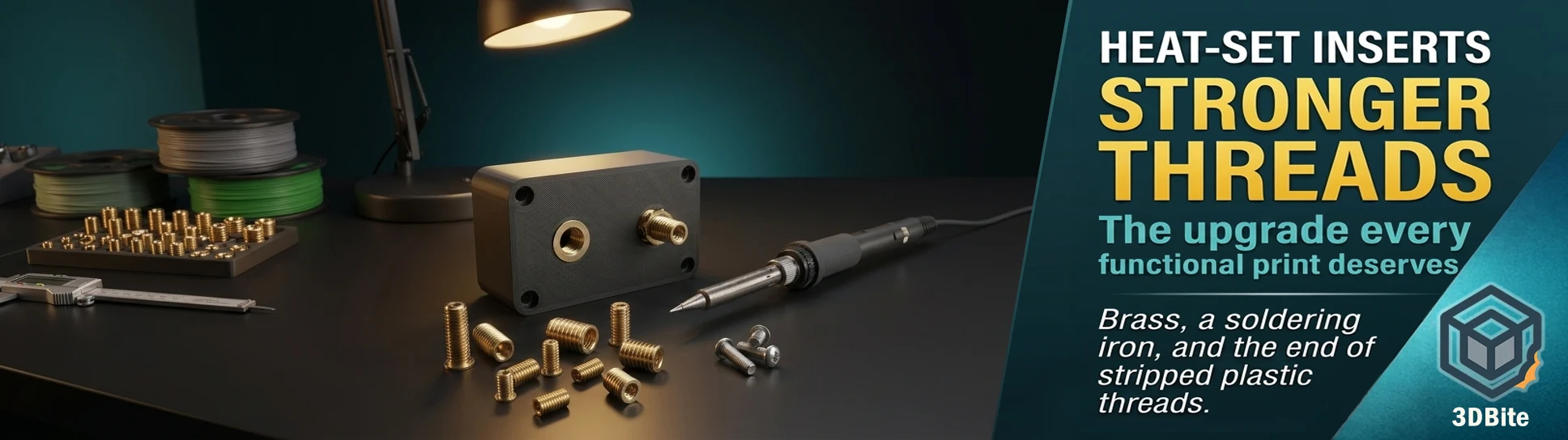
3D printed threads are one of those capabilities that sounds better than it is in practice. Printing a hole and tapping it, or designing a threaded feature directly into the model, produces something that works for the first few assembly cycles and then gradually becomes loose, stripped, and unreliable as the plastic deforms under the repeated compressive and shear forces that a screw applies. The material problem is fundamental: plastic is softer than metal, and metal screws threading directly into plastic holes will always win that contest over time, regardless of how well you printed the walls. The solution is not to print better threads. It is to embed metal threads directly into the plastic — and that is exactly what heat-set inserts do.
I have been using them for a while now, set with a standard soldering iron rather than a dedicated heat-set tool, and they work well without anything exotic in the toolbox. This guide covers what they are, why they work, how to size them correctly, how to design the hole geometry around them, and the installation process in detail — including the technique differences between a standard iron and a dedicated tip, and the specific things that produce a poor result if you get them wrong.
Why heat-set inserts work where printed threads do not
The insert is a small knurled brass cylinder with internal machine-screw threads. When you heat it and press it into a printed plastic hole, the surrounding plastic melts and flows into the knurled external surface, which is textured specifically to maximise the surface area bonding to the softened plastic. As the plastic cools and re-solidifies, it locks around the insert’s exterior in a mechanical grip. The insert is now positively captured in the plastic — not threaded in, not glued in, but physically locked by the cooled plastic conforming to its irregular outer surface.
The result is threaded metal inside a plastic part. When you thread a screw into the insert, it turns against brass rather than against PLA or PETG. Brass is substantially harder and more dimensionally stable than any common FDM printing material. The screw can be tightened, removed, and reinstalled repeatedly without the thread deforming, and the clamping force applied by the screw loads the insert against the plastic around it rather than loading the plastic thread itself. By melting inserts into parts, they are positively bonded to the plastic and no longer move. The screws are now turned into durable and also low-friction brass and thus will last effectively indefinitely.
The strength improvement over a directly tapped plastic thread is significant and comes from two sources. First, the thread itself is metal rather than plastic, so it does not deform under repeated fastening. Second, the circumference of the inserts is larger than the circumference of the fastener, meaning forces are distributed over a larger area of the part — the insert engages more of the surrounding material than a screw thread cut directly into the same hole would, spreading the load over a larger cross-section and reducing stress concentrations.
The types of insert and which to choose
Heat-set inserts for 3D printing come in several configurations. The most important distinctions for practical use are the thread standard (metric or imperial), the size, and the length style.
Thread standard: metric or imperial
Metric sizes — M2, M2.5, M3, M4, M5 — are the standard for most hobbyist and maker projects in the UK and EU, and for electronics-adjacent work where M2.5 and M3 screws are ubiquitous. Imperial sizes — #4-40, #6-32, #8-32, 1/4-20 — are relevant for US-format hardware, camera mounting threads, and any project that will be assembled with imperial fasteners. For the majority of functional 3D printing in a European context, M3 is where to start and where most projects stay.
Size: matching fastener to application
| Insert size | Typical use cases | Recommended wall thickness around insert |
|---|---|---|
| M2 / M2.5 | Electronics mounting, PCB standoffs, small enclosures, panel-mount components | 1.5mm minimum |
| M3 | General hobby assembly, Voron printers (standard), enclosure lids, battery holders, most functional prints | 2mm minimum |
| M4 | Medium structural connections, motor mounts, bracket-to-bracket joints | 2.5mm minimum |
| M5 | Heavy structural work, tripod/camera mount (3/8″ equiv), load-bearing fixtures | 3mm minimum |
| 1/4-20 | Camera thread standard — tripod sockets, camera mounts, accessory rails | 4mm minimum |
If you’re building a 3D-printed project and don’t have a specific screw size in mind, start with M3×0.5 Short inserts. They’re the most widely used size in the maker and 3D printing community, M3 screws are cheap and everywhere, and the Short style works in most standard wall thicknesses. An assortment kit covering M2 through M5 is the practical starting point — it covers the full range of likely applications without committing to a specific size until you know what the design demands.
Short vs Long: which length to use
Most heat-set inserts come in Short and Long variants. Short inserts are the standard choice for the majority of applications — they are easier to install flush, require less wall depth in the printed part, and provide adequate pull-out and torque-out resistance for most hobby and functional printing use cases. Long inserts have greater engagement depth and resist pull-out better under sustained axial load — relevant for parts that will be tensioned repeatedly or that carry significant load along the screw axis. For most printed enclosures, mounts, and assemblies, Short is the right choice. For structural parts with sustained loading, Long is worth the additional wall depth it requires.
Designing the hole: the most important step you do before printing
The geometry of the receiving hole determines more of the final result than the installation technique does. A correctly sized, well-placed hole with adequate surrounding material produces a strong, clean installation almost regardless of installation technique. An incorrectly sized hole produces a loose insert, a cracked part, or an unusable result regardless of how carefully the iron is applied.
Hole diameter
The receiving hole should be sized to the insert manufacturer’s specified outer diameter — typically very close to the insert’s major outer diameter, which is slightly smaller than the insert itself. The insert is designed to be pressed into a hole that requires the plastic to deform and flow around it rather than a hole the insert simply drops into. The specific dimension varies by manufacturer and size — always use the datasheet dimensions for the specific insert brand you are using, since different manufacturers have slightly different outer profiles. As a starting point, a general rule is that the hole diameter should be 0.3–0.5mm smaller than the insert’s outer diameter, but verify against the specific insert specification before printing.
FDM printers produce holes that are consistently slightly smaller than their designed dimension due to plastic shrinkage and extrusion overlap at the perimeter. This actually works in your favour for heat-set inserts — a hole printed at the manufacturer’s specified diameter will typically print slightly undersize, which is the correct starting point. If you find your inserts are loose after installation, reduce the hole diameter by 0.1mm and reprint the test feature. If the inserts require excessive force to start, increase by 0.1mm.
Hole depth
The hole depth should match the insert length plus approximately 0.5mm of additional depth. The extra depth gives the displaced plastic somewhere to go as the insert descends — without it, the melted plastic has nowhere to evacuate except back out around the top of the insert, creating a raised collar of plastic around the insert rim that prevents it from sitting flush. A counterbore is the correct design approach for a blind hole: a shallow wide section at the top for the insert’s flange (if present) and a narrower section below for the insert’s body. The counterbore depth should be sized to bring the top of the insert to exactly flush or 0.1–0.2mm below the surface when fully seated.
Wall thickness: the overlooked constraint
If you have less than 2mm of material around and below your insert, consider dropping to a smaller size. This is the constraint most often violated by designers who have not used inserts before. The plastic wall around the insert must be thick enough to capture and hold the insert against the forces applied by the screw. A wall that looks adequate visually on a 256mm model may be only 0.8mm of plastic in the critical zone around an M4 insert — too little to resist pull-out under normal fastening torque. Design the boss (the raised cylinder of plastic that surrounds the insert hole) to the minimum wall thickness in the table above, and orient the insert so that the material thickness in the primary load direction is maximised.
Wall count in the slicer directly affects this. Design the 3D-printed heat-set mounting point with a wall thickness set to a multiple of your extrusion width. This ensures that the walls will be printed with solid perimeters with no voids from infill. A boss designed with a total wall thickness of 2mm that happens to be printed as a single 1.2mm perimeter plus infill is structurally different from the same boss printed as two full perimeters. Set walls to at least three perimeters in the slicer for any section that includes a heat-set insert. In Bambu Studio, this means setting Wall Count to 3 or higher in the Process settings for the relevant part, or using modifier geometry to apply higher wall counts specifically to the boss areas without increasing wall count across the entire model.
Materials: which filaments work and how they differ
Heat-set inserts are suitable for virtually all thermoplastics — all materials used on an FDM printer. The installation temperature varies with the material’s glass transition temperature, and getting this right matters for both insert strength and part integrity.
| Material | Recommended iron temperature | Notes |
|---|---|---|
| PLA / PLA+ | 200–230°C | Lowest temperature range. PLA softens readily and the inserts set quickly. Risk of over-softening surrounding area if iron temperature is too high or dwell time too long |
| PETG | 225–250°C | Slightly more heat required than PLA. PETG’s higher toughness makes it an excellent insert material — good pull-out resistance after installation |
| ABS / ASA | 250–270°C | Higher temperature required. ABS flows well around inserts and produces strong installation. Enclosure or stable temperature environment helps prevent warping during installation |
| Nylon (PA6 / PA12) | 260–280°C | Highest common FDM temperature. Nylon’s hygroscopic nature means moisture in the filament can produce bubbling during installation — ensure thoroughly dried material |
| PCTG | 230–250°C | Similar to PETG. PCTG’s superior toughness over PETG makes it particularly well-suited for insert-based assemblies |
The general principle from CNC Kitchen’s documentation: select a temperature of approximately 10–20°C higher than the printing temperature for the material. For PLA printing at 215°C, this means 225–235°C for insert installation. For PETG printing at 235°C, 245–255°C is appropriate.
The installation process: standard soldering iron
The standard soldering iron method — which is exactly what I use — is fully adequate for all common insert sizes up to M5. The technique is straightforward but specific, and the specific parts of it matter for the result.
Step 1: Set temperature and wait. Set the iron to the target temperature for your material and wait until it is fully at temperature. A cold or partially warm iron will not transfer heat efficiently to the insert, producing an installation that requires force before the plastic has properly softened — which pushes the insert in crooked.
Step 2: Position the insert on the hole. Many inserts are slightly tapered on one end. Place the insert on the hole with the smaller diameter facing down — the taper helps centre the insert at the entrance to the hole before any heat is applied. If the insert has no taper, use tweezers to hold it vertical while you begin heating. Some inserts are tapered on one end to make inserting them easier. Once in place, turn on the soldering iron and let it heat up to the melting point of the material you are using, or just below. Then place the tip of the soldering iron onto the insert itself, making sure not to touch the plastic with the soldering iron directly.
Step 3: Apply heat to the insert, not the plastic. Touch the iron tip to the top of the insert and apply light downward pressure. The heat conducts from the iron through the brass insert into the plastic below, softening it from the bottom up. The insert will begin to descend slowly as the plastic beneath it softens. Do not press hard — let the heat do the work. Forcing a partially-heated insert produces a crooked result because the plastic is not uniformly softened around the insert’s circumference.
Step 4: The 90% rule. Press the insert to approximately 90% of its full depth using the iron. Always melt the inserts only to about 90% of the depth with the soldering iron tip and do the last, short distance with a tool — a flat-ended metal rod, the side of a screwdriver blade, or anything flat and rigid that can press the top of the insert flush with the surface. Removing the iron at 90% and completing the installation with a non-heated tool prevents the iron from touching the surrounding plastic surface as the insert reaches flush depth.
Why the last 10% matters: As the insert reaches flush depth, the gap between the iron tip and the surrounding plastic surface reduces to essentially zero. A tapered standard soldering iron tip at this point is very likely to make contact with and melt the plastic surface around the insert, creating a cosmetic blemish and potentially a structural weakness. Completing the installation with a flat tool rather than the iron keeps the iron clear of the surface at the critical moment.
Step 5: Hold flush and wait. After the insert is at depth, hold the flat tool against it with light pressure for 20–30 seconds while the plastic re-solidifies. The inserts have a tendency to move slightly out of the component immediately after melting as the re-solidifying plastic attempts to push them back. Maintaining light pressure through the solidification period keeps the insert fully seated.
Step 6: Allow full cooling before fastening. Let it rest for three minutes to cool to a safe temperature. If you try to install a fastener in the insert too early, it will distort the hole and weaken the insert’s hold as the insert and the plastic around it will be too hot. Three minutes feels longer than it needs to be on a bench with other things to do, but the bond between insert and plastic is still forming during this period and early loading disrupts it.
The standard iron tip: the one real limitation
The most specific risk of using a standard tapered soldering iron tip rather than a dedicated insert tip is well documented in the Hackaday community guide and deserves explicit mention: if you use a tapered soldering iron tip, you risk getting the iron tip stuck in the insert. Metal expands when it heats up and contracts when it cools. As you install the insert, heat is dissipating from the insert into the part, causing the heated insert to cool slightly and also contract around the iron tip. The net result is when you try to pull the iron tip out, the insert comes with it.
The solution when using a standard iron is straightforward: use the side of the tip rather than the point, maintaining contact with the insert’s top surface without inserting the tip into the bore. This transfers heat effectively, maintains control over the depth, and avoids the contraction-grip problem. The 90% rule also helps — if you are completing the final depth with a non-heated flat tool, the iron tip’s contact with the insert is already limited and the stuck-tip risk is reduced.
Dedicated insert tips — available as Hakko-compatible accessories and from several specialist suppliers — are flat or cylindrical rather than tapered, sized to fit into the top of a specific insert diameter without inserting deeply enough to risk contraction grip. They produce cleaner, more repeatable results, particularly for M4 and M5 inserts where the iron’s tip geometry matters more. For occasional M3 insert work with a standard iron and good technique, a dedicated tip is a nice-to-have rather than a requirement. For regular multi-size insert work or for production quantities, the investment in a set of dedicated tips pays back quickly in fewer ruined parts.
Common problems and what causes them
| Problem | Most likely cause | Fix |
|---|---|---|
| Insert sits proud of the surface — will not go flush | Hole too shallow or hole diameter too large (insert floats rather than sinks) | Increase hole depth by 1mm. Reduce hole diameter by 0.1mm and reprint |
| Insert goes in crooked | Too much force applied before plastic fully softened, or iron not perpendicular | More patience — let heat do the work. Use tweezers to hold insert vertical until heat establishes |
| Plastic melts and flows up around insert rim | Hole too shallow with no depth for displaced material, or too much heat | Add 0.5mm depth below insert. Reduce iron temperature slightly |
| Insert spins when tightening screw | Hole too large — not enough engagement between knurling and plastic | Reduce hole diameter by 0.1–0.2mm and reprint |
| Insert pulls out under load | Insufficient wall thickness or insufficient insert depth in part | Increase boss wall thickness. Consider Long insert variant. Increase infill and perimeter count in the boss zone |
| Iron tip stuck in insert | Tapered tip inserted into bore, heat dissipated, brass contracted onto tip | Use side of tip not point. Switch to dedicated insert tip. Apply reheating briefly to re-expand before pulling |
| Plastic cracked around insert | Hole too small or wall too thin. Excessive force during installation | Increase hole diameter by 0.1mm. Increase wall thickness. Let heat work before applying pressure |
When to use heat-set inserts and when you do not need them
Heat-set inserts earn their place in every functional print that requires any of the following: repeated disassembly and reassembly, screws that will be torqued to any meaningful level, structural connections where screw pull-out is a failure mode, or long-term fastened connections that need to remain tight over months or years of use. Electronics enclosures, panel mounts, tool holders, camera mounts, robot and drone parts, RC vehicle components, workshop jigs and fixtures — all of these benefit directly.
Where they are less necessary: one-time assembly joints where the parts are fastened and not expected to be disassembled again, non-structural snap-fit connections, or parts that will be replaced regularly where thread condition is irrelevant to the design lifetime. For those cases, self-tapping screws into printed holes or designed-in snap features are adequate and simpler. The insert earns its overhead specifically when the thread needs to survive repeated use.
Summary
Brass heat-set inserts are one of the cheapest and most reliable functional upgrades available for 3D printed parts. A £5 assortment kit covering M2 through M5 covers the vast majority of applications. A standard soldering iron at 220–270°C depending on material does the installation without any additional tools needed. The technique — heat to the insert not the plastic, use the side of the tip not the point, press to 90% with the iron and the final 10% with a flat tool, hold flush through solidification, wait three minutes before fastening — produces reliable, professional results once it becomes muscle memory after the first few installations.
The design side is where most failures originate. Correct hole diameter, adequate depth, and sufficient wall thickness around the boss are the three parameters that determine whether the insert holds or fails, and all three need to be correct in the model before printing rather than corrected at the bench. Get those right, apply the installation technique consistently, and you will find that the quality of assembled functional prints improves noticeably — the difference between parts that feel assembled and parts that feel engineered is frequently just the decision to use a brass thread rather than a plastic one.