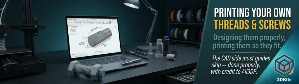
All3DP published a genuinely useful guide on printing your own threads and screws — Threads & Screws: 3D Print Them Perfectly Every Time, written by Miroslav Sarcevic and Lauren Fuentes. It walks through the CAD side properly, which is a topic most 3D printing content skips over in favour of jumping straight to slicer settings. Full credit to All3DP and the original authors — the piece is worth reading in full, and it is licensed under Creative Commons Attribution 4.0, which the original explicitly states at the foot of the article. This post is our own pass through the same territory, restructured with our own emphasis and connected to the heat-set insert coverage already on this site, because the two topics sit right next to each other in any conversation about functional printed parts.
The relationship this site has already had with this topic
The heat-set inserts post made a specific argument: printed plastic threads deform under repeated fastening, and the fix is embedding a metal insert rather than relying on the plastic thread to hold up over time. That argument stands. But it is not the whole story, because heat-set inserts are the right tool for a specific job — repeated disassembly, meaningful torque, long-term reliability — and there is a genuinely large category of printed threaded parts where a real, properly designed printed thread is entirely the correct choice: prototypes, one-time assemblies, low-stress connections, and anything where the thread only needs to hold for the life of a display piece or a single use rather than years of repeated fastening. Getting a printed thread to actually work — fit correctly, screw together smoothly, hold under the load it is meant to carry — is a distinct skill from the insert workflow, and it is the one All3DP’s guide covers thoroughly.
The terminology worth actually knowing
A thread is a continuous helical groove cut or formed around a cylindrical surface, and it is the fastening feature — not the same thing as a screw, which is the fastening element that uses a thread to form a joint that can later be taken apart. This distinction matters because threads show up well beyond screws: pipes, worm gears, linear drive lead screws, and plenty of mechanisms printed for entirely non-fastening purposes.
External (male) threads extend outward from a cylindrical surface — a bolt is the obvious example. Internal (female) threads are cut into the inside of a cylindrical void — a nut, or any threaded hole. Thread direction matters more than people assume: the overwhelming majority of threads are right-handed, screwing in clockwise, but left-handed threads exist deliberately in specific places — the hot water tap in a shower or sink is the classic real-world example — specifically so the two cannot be confused or cross-threaded by mistake.
The dimensional vocabulary is worth having precisely rather than approximately, because getting these wrong is exactly how a printed thread ends up not fitting its mating part. The major diameter is measured to the outer crest of an external thread, or to the root of an internal one. The minor diameter is the reverse — the root of an external thread, or the crest of an internal one — and is sometimes called the drill size diameter for internal threads specifically. Pitch is the distance between equivalent points on adjacent thread turns — crest to crest, essentially. These three numbers, plus thread direction and the standard being followed, fully define any thread you are trying to reproduce or design from scratch.
Metric versus inch: know which one you are working in
Metric threads, denoted with an M prefix, specify the nominal outer diameter directly in millimetres — an M5 thread has a 5mm major diameter on its external form. Inch threads follow the Unified Thread Standard, typically naming smaller sizes by number (a #4 screw, for instance) and specifying threads per inch (TPI) as the equivalent of pitch. Getting these systems confused — assuming a UK or European part is metric when it is actually a UTS inch thread, or the reverse for a US-sourced part — is a genuinely common source of a printed thread that looks correct on screen and simply will not mate with the real hardware it was meant to fit. Before designing anything intended to mate with an existing physical part, identify which standard that part actually uses rather than assuming.
Two ways to get the geometry: toolbox parts versus modelling from scratch
Most CAD packages ship with libraries of standard hardware — SolidWorks has its Toolbox, Fusion 360 integrates with the McMaster-Carr add-in directly inside the Design workspace, letting you search and drop in a correctly-dimensioned screw, threaded rod, washer, or nut without modelling anything by hand. For any application using a genuinely standard fastener size, checking whether your CAD package’s library already has it is worth doing before modelling from scratch — it is faster and removes any risk of a dimensional mistake.
The specific warning worth repeating from the original article: some CAD software’s simplified thread display modes are cosmetic only. Certain SolidWorks display settings show a thread-like surface that is not actually a continuous helix at all — just a single circular cut repeated in one plane, visually resembling a thread but geometrically non-functional. Printing one of these produces a part that looks correct in the slicer preview and does not actually screw together. Before committing plate time to any threaded part sourced from a library or an unfamiliar modelling tool, verify the thread is genuinely helical rather than a flat visual approximation.
For threads with no ready-made library part, Fusion 360’s built-in Thread tool is the accessible route: sketch a circle at the major diameter, extrude it to the thread’s length, then use Create → Thread on the resulting cylinder, ensuring the “Modeled” option is checked rather than left on a cosmetic display mode, and set the thread type and parameters to match the standard you are targeting. Internal threads follow the same logic in reverse — model the surrounding body, cut a hole at the major diameter, then apply the Thread tool to the internal surface of that hole with Modeled checked.
Material choice: this connects directly to what has already been covered here
A screw thread carries considerable force along its axis, and every one of those layers is a bonded interface rather than continuous material — precisely the anisotropic weakness covered at length in the print orientation post. PLA, printed with the thread axis running vertically through many stacked layers, can snap at the weakest layer boundary under load that a stronger material would tolerate easily. This is the specific mechanism that pushes any load-bearing printed thread toward ABS or nylon rather than standard PLA, and it is worth reading alongside the orientation post’s broader point: the choice of material and the choice of print orientation are solving the same underlying problem from two different angles, and doing both properly compounds the benefit rather than either one alone being sufficient.
The print settings that actually matter
Orientation is the first and most consequential decision, and it is a direct trade-off rather than a single right answer. Printing the thread axis vertically means fewer supports and less post-processing, but produces a structurally weaker result because the load runs straight through the stack of layer boundaries. Printing horizontally, with the thread axis running parallel to the bed, produces a stronger result because the load path runs more through continuous extruded plastic — exactly the orientation logic from the orientation post applied to this specific geometry. For anything genuinely load-bearing, horizontal wins; for a display piece or a low-load application, vertical’s reduced support and cleanup requirement is the reasonable trade.
Keep supports out of the thread geometry entirely wherever possible — support material generated inside a threaded bore, particularly an internal one, is genuinely difficult to remove cleanly without damaging the thread profile, and a damaged internal thread is often unusable rather than merely cosmetic.
Wall count and infill both matter for thread durability specifically. At least four perimeter walls, or roughly 2mm of solid wall thickness around the threaded feature, gives the thread body enough structural backing to resist deformation under load — thin single-perimeter walls flex under thread engagement force in a way that undermines the whole point of printing a functional thread. Infill density of at least 25% is the sensible baseline for anything load-bearing; lower infill leaves the thread’s supporting body too hollow to resist compression from the fastener being tightened into it.
Layer height governs how closely the printed thread profile approximates the intended smooth helical form — thinner layers produce a smoother, more accurate thread surface. As a working guide: threads above M12 (or larger than 1/2 inch) print acceptably at a standard 0.2mm layer height, while anything smaller benefits from a finer layer height to resolve the tighter geometry properly.
The size ceiling nobody mentions until it bites
This is the detail from the original article most worth flagging directly, because it explains a specific and common frustration. On a standard 0.4mm nozzle at 0.2mm layer height, the smallest reliably printable thread pitch is roughly 0.5mm — which happens to correspond to an M3 thread, one of the most commonly needed small fastener sizes in this hobby. Below that, printed threads become genuinely unreliable, and the geometry the nozzle is being asked to resolve starts exceeding what a 0.4mm extrusion width can physically represent with any precision.
Internal threads at this small scale have an easier time than external ones for a specific mechanical reason: while the nozzle is elsewhere on the layer, the just-printed section of an internal thread has time to cool before the nozzle returns to it. An external thread on a standalone screw or bolt offers the nozzle nowhere else to go — it is continuously depositing material right where it just was, with far less cooling time between passes, and this is exactly where thin external threads are most prone to problems and most benefit from the aggressive cooling fan settings covered in the bridging post, since a fine external thread wall is functionally a very short, very frequent bridging challenge repeated around the full circumference many times over.
Below roughly M6, a printed external thread is realistically decorative rather than load-bearing — fine for a display model, not appropriate for anything expected to actually carry load. Below 4mm diameter on internal threads specifically, the pitch becomes small enough that a different approach altogether is often more reliable: print a plain, unthreaded hole at the correct diameter and cut the actual thread afterward with a tap and wrench, the same mechanical thread-cutting process used on metal. This produces a genuinely accurate, genuinely functional small thread that a nozzle simply cannot reliably reproduce at that scale.
The dimensional testing habit worth adopting
Different filaments shrink by different amounts as they cool, and this genuinely affects thread fit at the tolerances threads require. The sensible habit before committing to a large threaded part: print a small test sample of the same thread geometry first, check the actual fit, and adjust the model dimensions if the result comes out too tight (common on internal threads, since the material shrinks inward around the void) or too loose (more typical on external threads, where the printed material shrinks away from its intended outer profile). This costs a few minutes and a small amount of filament, and it is the difference between a first attempt that fits correctly and a full-size print that has to be scaled and reprinted after the fact.
Where this leaves the printed-thread-versus-insert decision
Bringing this back to where it started: a properly designed and properly printed thread, following the guidance above, is a genuinely viable functional feature for the right application. It is the correct choice for prototypes, one-off assemblies, display pieces, and anything that will be fastened once or a handful of times rather than disassembled and reassembled repeatedly. Heat-set inserts, covered in the earlier post, earn their place specifically where repeated fastening cycles, meaningful torque, or long-term reliability are the requirement. Neither approach is universally correct — knowing which situation calls for which is the actual skill, and understanding how a printed thread is properly designed, as the All3DP guide covers thoroughly, is what makes that choice an informed one rather than a default.
Full credit again to Miroslav Sarcevic and Lauren Fuentes at All3DP for the original piece — read it in full at all3dp.com, particularly for the step-by-step Fusion 360 walkthrough with screenshots, which is more useful followed directly from the source than summarised here.