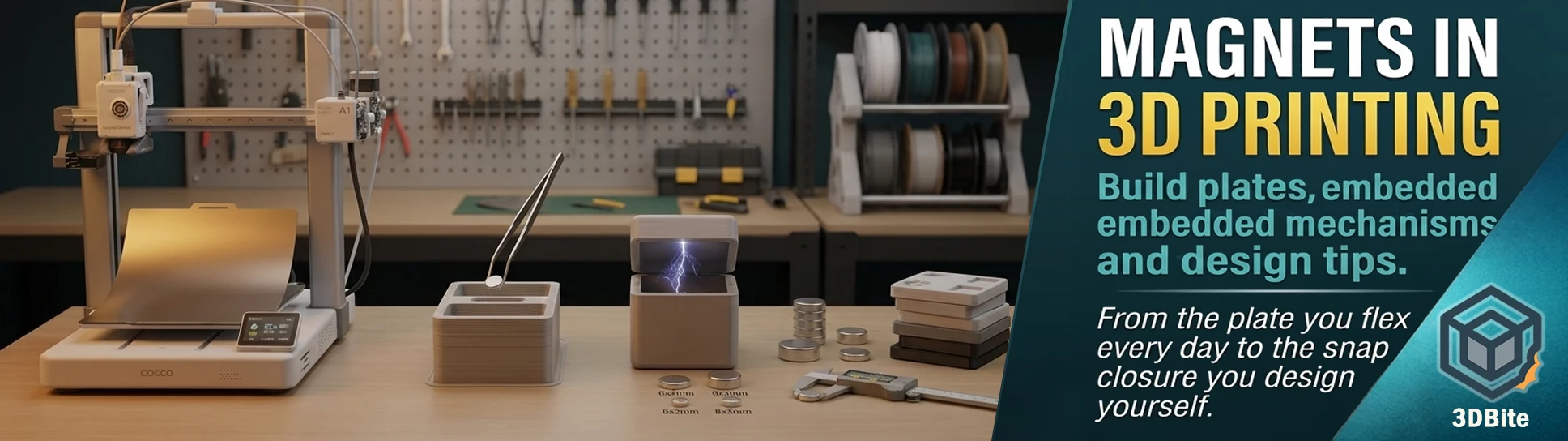
Magnets turn up in 3D printing in more ways than most people stop to think about. The most visible is the build plate — every time you peel the A1’s plate off the bed and flex it to release a print, you are relying on magnets. But that is only the start of it. Embedding neodymium magnets into printed parts opens a range of design possibilities that screws and clips simply cannot replicate: closures that snap shut, parts that self-align, assemblies that disassemble with a pull and reconnect with a satisfying click. This post covers the full picture — how the magnetic build plate actually works, how to embed magnets into prints properly, what designs benefit most, and where the traps are.
The magnetic build plate: how it actually works
The magnetic spring steel build plate system that Bambu, Prusa, Voron, and essentially every modern FDM printer uses is a three-layer sandwich that solves several problems simultaneously. At the bottom is the heated aluminium bed, which provides the thermal mass and heating element. On top of that, adhered with high-temperature 3M tape, is a flexible magnetic sheet — a thin ferrite or neodymium-loaded rubber or silicone layer that provides the magnetic field. On top of that sits the removable spring steel plate with its PEI or textured coating, held in place purely by the attractive force between the steel and the magnetic sheet beneath it.
The spring steel’s magnetic properties are what make this work rather than just the steel being attracted to a magnet below. Spring steel is chosen specifically because it is magnetically permeable — it responds to the magnetic field — while also having the spring-back properties that allow the flex-to-release removal method. When you peel the plate off the printer, the magnetic hold releases cleanly at the interface between the spring steel and the magnetic sheet. When you flex the plate after removal, the print’s bond with the PEI surface breaks cleanly because the spring steel’s deformation creates a shear force at the boundary between print and plate that peeling from above cannot. The whole system relies on the magnetic hold being strong enough to keep the plate stable during printing and weak enough to release cleanly when you want to remove it.
The temperature behaviour of the magnetic sheet is worth knowing. Standard ferrite-based magnetic materials begin to lose magnetic strength at elevated temperatures, and the magnetic sheet in a heated bed setup is being cycled repeatedly between room temperature and whatever the bed runs at. Most magnetic sheets used in consumer 3D printer build plate systems maintain adequate holding force up to 80-100°C, which covers PLA and PETG operating ranges. For materials that require bed temperatures above 100°C — ABS, ASA, Nylon — some magnetic sheets lose enough force at temperature that the plate can slide or lift at the edges during printing, which is one reason high-temperature printing is harder on build plates and magnetic systems than standard PLA work. Bambu’s own magnetic sheets are rated for the temperatures their hardware supports, but third-party magnetic bases on machines running consistently hot beds should be checked for their rated temperature range before assuming they will hold reliably.
The full build plate guide covering the different surface types — textured PEI, smooth, holographic, and others — is at the build plates complete guide, and the holographic plates discussed in the holographic guide all use the same magnetic spring steel format. The magnetic system is the delivery mechanism; the surface coating is the variable that changes between plate types.
Kinematic magnetic bed mounts: the precision engineering application
A step beyond the standard magnetic plate system, and one that appears more often in the DIY and Voron community than in consumer machines, is the magnetic kinematic mount for the bed itself. Rather than the bed being screwed down to the frame, a kinematic mount uses three magnetic contact points — typically small neodymium magnets paired with precision steel balls — to locate the bed in exactly the same position every time it is removed and replaced. The geometry of a three-point kinematic mount means that three constraints define a plane uniquely, so a bed that is removed for cleaning, plate swapping, or maintenance returns to the identical position within microns when replaced.
This matters for machines that do not run automatic bed levelling before every print, or where the user wants to skip the levelling routine because they know the bed is in the right position. The magnetic force holds the bed firmly during printing; the kinematic geometry ensures repeatable position. The Voron community has developed and documented this approach extensively, and it is now commonly used in enthusiast builds as a practical alternative to the levelling screws and spring-loaded adjustment mechanisms that conventional beds rely on. The A1 and A2L use automatic bed levelling before every print rather than kinematic mounts, so this is not an A1-specific concern — but it is an example of magnets solving a precision engineering problem in a non-obvious way.
Embedding magnets in printed parts: the basics
This is where magnets move from being part of the printer to being part of what the printer makes. Embedding a neodymium magnet into a printed part — a closure, a connector, a mounting point, a self-aligning joint — requires designing a cavity into the model, placing the magnet during or after printing, and either press-fitting it or securing it with glue. Done well, the result is a printed object with invisible magnetic functionality: a lid that snaps shut, a modular system that assembles and disassembles without tools, a display piece that mounts to any steel surface.
Which magnets to use
Neodymium magnets — the small, strong rare-earth magnets — are the right choice for almost every embedded application in FDM-scale printing. They are available in disc, cylinder, and block shapes from AliExpress, Amazon, and specialist suppliers at low cost. The grade designation (N35, N42, N52) indicates magnetic strength — N52 is the strongest readily available consumer grade, N35 is weaker and cheaper. For most closure and alignment applications, N35 or N42 is adequate and costs less. For small-footprint applications where maximum force in a small volume is needed, N52 is appropriate.
The most commonly used sizes in the 3D printing community are a handful of standards that have become de facto norms because they appear in so many MakerWorld and Printables designs: 6×2mm discs for general closure and alignment, 8×3mm for stronger holding applications, 10×3mm for heavier loads, and 5×1mm for very thin wall designs. Before designing your own cavity around a magnet, checking what sizes the magnet retailers you plan to use actually stock reliably saves the frustration of designing for a size that takes four weeks to arrive.
Two embedding methods and when to use each
The glue-after-printing method designs a cavity of appropriate depth and diameter into the model, prints the whole part, and inserts the magnet after printing using superglue or epoxy to secure it in place. The cavity diameter should be 0.1-0.2mm smaller than the magnet’s actual diameter to give a snug press fit before gluing — this prevents the magnet from moving while the glue cures and produces a cleaner result than a loose cavity relies on glue alone to fill. The advantage of this method is that it works with any filament, any print settings, and any slicer without any special configuration. The disadvantage is that the magnet cavity is open on one face, meaning the magnet is visible on the surface of the part rather than fully enclosed.
The pause-and-insert method encloses the magnet completely inside the printed part. You pause the print at the layer where the magnet cavity is just deep enough to hold the magnet, drop the magnet in, and then resume printing above it. The subsequent layers print over and seal the magnet inside the part. In Bambu Studio this can be set up using the “Pause at Layer” feature in the filament menu under the layer view. In OrcaSlicer the equivalent is a layer-specific pause command. The result is a magnet that cannot be seen, cannot fall out, and cannot be reached — useful for consumer products, children’s toys, or anything where the magnet coming loose is a safety or reliability concern. The practical risks: if the print fails or you miss the pause notification, you may need to restart. And the magnet must be oriented correctly — polarity relative to the mating part — before the print resumes, because there is no correcting it afterward.
Polarity: the trap that catches everyone at least once
Neodymium magnets attract from one pole and repel from the other. When you are designing a mating pair — two parts that should snap together — the magnets in each part need to have their north and south poles oriented so that they attract when the parts come together rather than repel. This sounds obvious and is consistently the mistake that requires restarting either a post-print glue step or, worse, a pause-and-insert print where the magnet went in backwards.
The reliable approach before embedding any magnets: stack the full set of magnets you are going to use in the correct orientation, mark each one with a paint marker dot on the north face (or whichever consistent face you choose), and lay them out in the orientation they will go into the part before you start embedding. For a two-part box with four magnets — two in the lid, two in the base — all four magnets should be tested together, verified to attract when the lid and base are brought together, and then marked consistently before any go near glue or a printing pause. It adds five minutes to the process and eliminates the most common failure mode.
Design considerations for magnetic cavities
Wall thickness around a magnet cavity affects both structural integrity and magnetic field transmission. The magnetic force between two embedded magnets passes through the material between them — a thinner wall allows more force to reach the mating part, but below about 1.5mm the structural strength of the cavity wall becomes a concern and the magnet can crack out under repeated assembly and disassembly cycles. Two to three perimeters of material around the cavity side walls, and at least two layers of printed material above a fully enclosed magnet, is the practical minimum for structural reliability.
The print orientation of the part relative to the cavity matters more than it might appear. A magnet cavity that has its open face pointing upward during printing — toward the nozzle — benefits from clean bridging over the cavity before the magnet is inserted. A cavity that has overhanging geometry on its inner walls during printing may produce rough internal surfaces that prevent the magnet from seating fully flush, which reduces the magnetic force and may prevent the part from mating correctly. Design the cavity so that the bridge over it, if the magnet is enclosed, is as short as possible, and so that the cavity’s inner walls print without unsupported overhangs where possible.
What designs benefit most from embedded magnets
Closures and lids are the most common application and the most immediately satisfying — a box that snaps shut with a quiet click and pulls open with a deliberate tug is a better product than a press-fit lid that requires a screwdriver to open or a hinged design that breaks at the hinge after repeated use. The multi-part printing workflow covered in the multi-part printing post is a natural context for embedded magnets: multi-part figurines assembled from separately printed colour components can use magnet pairs at the joint locations to provide self-alignment and a secure connection that holds the parts in the correct orientation without relying entirely on adhesive. Print each part with a magnet cavity, embed matching pairs, dry-fit before any glue is applied to confirm alignment, then glue permanently. The magnets both locate the joint precisely and provide additional holding force alongside the adhesive.
Modular systems — shelving inserts, storage dividers, stackable containers, tool organisation — benefit from magnetic connectors because the connection is quick and tool-free while still being firm enough not to shift during use. A set of magnetic wall-mount hooks for a workshop can be repositioned without tools, adjusted without screws, and rearranged as the storage requirements change. The magnet force does the structural holding; the printed part shapes the storage.
Self-returning mechanisms use magnetic repulsion rather than attraction — two magnets with like poles facing each other push the moving part back to its start position when released. A button that clicks in and springs back out, a lever that returns to neutral, a sliding cover that pushes back when released. These mechanisms replace springs in printed designs and are more reliable than printed spring geometry, which fatigues and eventually fails in PLA. The repulsion force is predictable, adjustable by magnet grade and gap distance, and does not require the precision of a printed spring to function correctly.
Surface mounting is perhaps the most utilitarian application: a small recess of the right depth on the back of any printed object, a magnet pressed in, and the object can now be mounted to any refrigerator, tool cabinet, whiteboard frame, or steel surface without drilling or adhesive. For anything intended to mount on a steel surface — utility hooks, key fobs, magnetic cable organisers, decorative pieces, cable clips on a steel desk — the magnet-backed approach is cleaner and more reversible than any alternative.
The safety points worth knowing
Strong neodymium magnets — anything above N35 in a size of 8mm diameter or larger — deserve specific handling consideration in the context of printed objects. The choking hazard of small magnets is well understood and the reason the pause-and-insert full-enclosure method is the right approach for anything a child will handle. A fully enclosed magnet cannot fall out and cannot be reached. A glued-in magnet in an open cavity is one failed glue joint from being accessible. For prints intended for children, enclose magnets completely inside the printed part during printing and never rely on adhesive alone to retain them.
Pinching injuries from large neodymium magnets during handling are a real risk — a pair of N52 magnets larger than 15mm diameter can close together with enough force to trap and bruise skin. During assembly and testing of magnetic designs, handle strong magnets cautiously, especially when orienting and checking polarity with pairs in hand.
Electronic devices — smartphones, hard drives, pacemakers — maintain a sensible distance from strong embedded neodymium magnets. Printed organiser systems with embedded magnets kept near a phone or computer are generally low risk at the small magnet sizes typical of FDM-scale embedding, but it is worth being aware of the field the magnets generate rather than treating them as inert hardware after enclosure.
Magnets in the printer itself
Beyond the build plate, magnets appear in the printer in more places than most users realise. The AMS Lite uses magnets in its spool detection and filament path components. The toolhead on the Vortek H2C uses inductive coupling, which is adjacent to magnetic field engineering even if not directly magnetic. The Bambu machine’s bed levelling system includes a hall-effect sensor — a magnetic field sensor — as part of the auto-levelling assembly. Even the idler pulleys in some printer designs use magnets to prevent slippage at high speeds.
Awareness of this matters in one practical context: storing strong neodymium magnets near the printer’s toolhead, mainboard, or AMS components while working with embedded magnet designs. The printer’s own magnetic components are engineered and shielded, but deliberately bringing a strong external magnet close to the toolhead or electronics during printing or setup is worth avoiding. Keep the magnet stock away from the machine while printing, bring them to the bench only for embedding and testing.
Where to get started
A small assortment of standard-size neodymium magnets covers the overwhelming majority of what hobbyist embedded magnet printing requires. A pack of 6×2mm N35 disc magnets and a pack of 8×3mm N35 discs is the starting stock — between them they suit most closures and alignment applications and are the sizes that appear most frequently in MakerWorld models with embedded magnet specifications. Buying in multipacks rather than individual magnets reduces the per-unit cost significantly on AliExpress; just order in advance of needing them rather than expecting next-day delivery. A tube of gel CA and a tube of two-part epoxy from the adhesives guide completes the embedded magnet setup.
Browse the MakerWorld and Printables libraries with the search term “magnet” added to any model category you are interested in and you will find hundreds of examples of embedded magnet design done well, with specific magnet size specifications in the model notes. These are the fastest way to understand what working embedded magnet geometry looks like in practice before designing your own cavities from scratch.