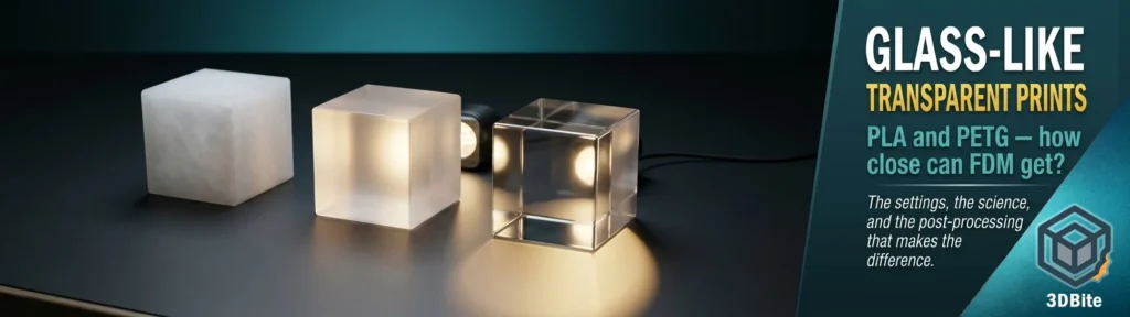
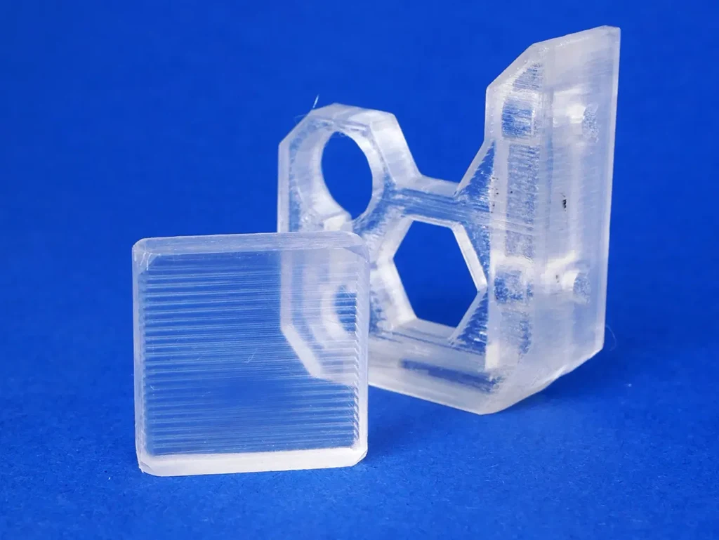
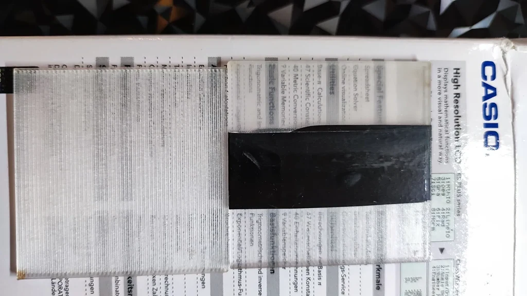
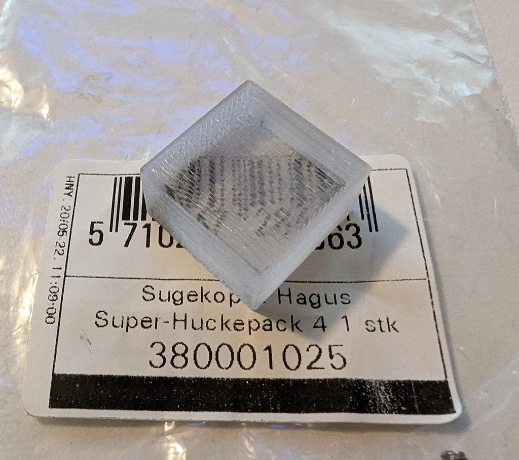
Let us be honest with each other upfront: FDM printing will not produce prints as transparent as glass. The key word to manage expectations here is translucent, not transparent. Think of frosted glass blocks — light passes through and diffuses, creating genuinely beautiful effects, but without the window-pane clarity of optical glass. If you need a lens-quality clear result, resin printing is the correct technology. If you want the best translucency that FDM can deliver — and with the right settings it can be considerably better than most people realise — this post covers exactly how to get there on a Bambu machine.
PETG is meaningfully better than PLA for this application and we will explain exactly why before getting into settings. But both materials can produce impressive results with the right approach, and for certain models and purposes an opaque or semi-opaque result can be exactly what you want — diffusing light evenly rather than transmitting it clearly, which has its own aesthetic appeal. The settings differ significantly between the two materials, and the post-processing options open up further after the print comes off the plate.
Why PETG is better than PLA for transparency
The reason comes down to polymer structure. PLA is a semi-crystalline polymer — the crystalline grains within it affect light refraction. PETG is an amorphous polymer. Therefore, PETG generally has higher transparency than PLA. This is not a settings difference or a quality difference between specific filament brands. It is the fundamental material science of how these two polymers are structured at the molecular level.
PLA’s semi-crystalline structure means that even in an ideal print with perfect settings, there will be light scattering at the crystal boundaries within the material itself. You can minimise the external surface scattering with good settings, but you cannot eliminate the internal structural scattering. PETG’s amorphous structure has no crystal boundaries — light passes through a more uniform medium. The best transparent PETG print will always outperform the best transparent PLA print from the same nozzle on the same machine.
This does not mean transparent PLA is not worth printing. For diffusion effects, light panels, lamp shades, and decorative objects where a frosted or milky light transmission is the desired effect, PLA’s natural translucency character can actually be preferable. Knowing which you want — maximum clarity or even diffusion — helps you choose the right material before you start.
Why FDM prints are cloudy: the physics
Understanding the cause of cloudiness is what makes the settings make sense rather than feeling like arbitrary adjustments. There are three distinct causes of opacity in a transparent filament print.
First, air gaps between layers and between extrusion lines. Any void in the print is an air-filament boundary where light refracts and scatters. The goal of the settings is to eliminate these voids by ensuring the filament flows slowly enough and hot enough to fuse completely with adjacent lines and layers.
Second, surface roughness. Layer lines on the outside of the print are physical ridges that scatter light at the surface before it even enters the material. A rough surface on a transparent print is like frosted glass — it diffuses rather than transmits. This is why the build plate choice, print speed, and post-processing all matter.
Third, the infill direction. You should ensure your hot end is just making long, straight strokes for layer after layer to best allow light to pass through. You’ll also want to maximise nozzle flow to avoid any unsightly gaps or bubbles in your print. When infill lines cross each other at an angle, they create points where light scatters at the crossing. Aligning all infill in a single direction means light travels through a more uniform structure of parallel filament rods rather than a crossed lattice.
The reference models and profiles
Before the settings, it is worth knowing about the community resources that have been rigorously tested and documented. These are the best starting points for calibration rather than starting from scratch.
- Test Model for Transparent PETG Printing — Printables model 273948 by Rygar1432 — the most widely referenced community calibration model for transparent PETG. Includes baseline settings that have been iterated by hundreds of users. Print this before attempting a real model
- How to Print Glass — Profile for PETG Transparent — Printables model 575217 — a Bambu-specific profile for transparent PETG with accompanying methodology for post-processing. Printed with SUNLU PETG Transparent on an X1C
- Printing Glass — Transparent PETG — MakerWorld model 40303 — Bambu Studio-compatible profile with community notes on Bambu-specific settings
- Bambu Lab Wiki — Transparent PETG printing guide — Bambu’s own official settings recommendations for transparent PLA and PETG on their hardware
PETG transparent settings: the full picture
These settings represent the consensus from Bambu’s own wiki, Rygar1432’s documented methodology, the Printables community, and MakerWorld user testing. They are demanding — the print will be slow and require patience — but they produce the best results achievable from FDM without post-processing.
| Setting | Recommended value | Why |
|---|---|---|
| Nozzle temperature | Upper limit of your filament’s range — typically 240–260°C for PETG. Start at 245°C | Hotter filament flows more completely, fuses better with adjacent lines, eliminates voids. Boiling or yellowing occurs if pushed too far — watch first few layers |
| Bed temperature | 80°C | Standard PETG bed temp. Smooth PEI plate is mandatory — see below |
| Build plate | Smooth PEI — mandatory | Textured plates leave their pattern on the bottom surface of the print, creating light-scattering roughness on the face that needs to be smoothest. Smooth PEI produces the clearest base layer |
| Layer height | 0.10–0.12mm | Thinner layers fuse more completely. 0.12mm is the community sweet spot between clarity and print time. Rygar1432’s baseline uses 0.12mm |
| Line width | 0.5mm (on 0.4mm nozzle) | Slightly wider than standard to increase overlap and reduce voids between lines |
| Wall loops | 1 | Multiple walls create more internal boundaries for light to scatter at. One wall, fully fused to the infill, produces the most uniform light path |
| Top shells | 0 | Remove top and bottom shells entirely — the 100% infill becomes the structure. Shells create separate layer interfaces that add scattering |
| Bottom shells | 0 | Same reason as top shells |
| Infill density | 100% | No air gaps. Any void is visible as a cloudy region |
| Infill pattern | Rectilinear (aligned) — all lines in a single direction at 0° or 90° | Parallel lines create a uniform light path. Crossing lines scatter light at every crossing point |
| Infill direction | 0° (or 90°) — do not alternate direction per layer | All lines running the same direction throughout the entire print means light travels through a consistent structure. Alternating layers destroy this |
| Part cooling fan | 0% — completely off | Rapid cooling prevents complete layer fusion. The filament needs time to settle and merge before solidifying. This is the most counter-intuitive setting and the most important one |
| Print speed | 15–25mm/s on all moves | Slow speed gives hot plastic time to settle and merge with the previous layer. Speed creates microscopic imperfections that scatter light. Patience is the price of clarity |
| Flow rate | 102% | Slight over-extrusion ensures complete fill with no gaps. Voids are the enemy |
| Retraction | Minimal — 1mm for Bambu machines. Do not over-retract | Excessive retraction on PETG causes heat creep and clogging risk at these temperatures. Community testing on P1S and X1C confirms 1mm is the safe maximum at transparent print settings |
| Filament drying | Dry for 24 hours minimum before printing | Moisture creates steam bubbles in the melt zone that show as white spots and voids in the finished print. Transparent filament exposes moisture defects more clearly than any other filament type |
PLA transparent settings: different considerations
PLA requires a different approach from PETG in two specific ways that matter significantly to the transparency result.
The fan cannot be fully disabled on PLA for most prints. Completely turning off the fan increases the risk of PLA warping, so it is necessary to moderately reduce the fan speed based on the needs and thickness of the model. For thin-walled transparent PLA prints — vases, panels, light diffusers — disabling the fan entirely causes the walls to collapse before they can support the next layer. The community approach is to run the fan at 20–30% for PLA rather than the 0% used for PETG. This is a compromise that reduces clarity compared to zero-fan PETG but keeps the print structurally sound. Thicker PLA models can tolerate lower fan settings; thinner geometry needs more cooling to maintain structural integrity.
The nozzle temperature for transparent PLA should also be at the upper end of the recommended range, but is typically lower than PETG — 210–220°C rather than 240–260°C. The principle is the same: hotter flows better and fuses more completely. The maximum safe temperature is constrained by the material — PLA begins to yellow or produce stringing at excessive temperatures, and the upper safe limit is lower than PETG’s.
| Setting | Transparent PETG | Transparent PLA |
|---|---|---|
| Nozzle temperature | 240–260°C (upper limit) | 210–220°C (upper limit of range) |
| Bed temperature | 80°C | 35–45°C on smooth PEI |
| Part cooling fan | 0% — fully off | 20–30% — minimum required for warp control |
| Layer height | 0.10–0.12mm | 0.10–0.12mm |
| Wall loops | 1 | 1 |
| Top / bottom shells | 0 / 0 | 0 / 0 |
| Infill density | 100% | 100% |
| Infill pattern | Rectilinear, single direction (0° or 90°) | Rectilinear, single direction (0° or 90°) |
| Flow rate | 102% | 102% |
| Print speed | 15–25mm/s | 20–30mm/s |
| Build plate | Smooth PEI (mandatory) | Smooth PEI (mandatory) |
| Maximum transparency achievable | Higher — amorphous polymer | Lower — semi-crystalline structure limits clarity |
Vase mode: the cleanest transparency for simple geometry
For objects like containers, vases, lamp shades, or any model that can be described as a hollow shell — vase mode is the single most effective setting for maximum transparency. In vase mode, the printer prints the outer wall in one continuous, spiraling motion. There are no Z-seams, no retractions, and no infill. It is the closest you can get to extruding a purely homogenous object. Combining vase mode with a slow print speed and a high temperature is a powerful technique for achieving stunning clarity.
Vase mode works because it removes the two biggest sources of opacity in the infill approach: the boundary between the wall and the infill (which creates a light-scattering interface even in a well-fused 100% infill print) and the Z-seam (where each layer starts and stops, leaving a vertical line of slightly different surface character). In vase mode, the extrusion is continuous from bottom to top with no interruption. The result is a single continuous helical extrusion that, with the right temperature and speed, fuses into a solid transparent shell.
The limitation is geometry. Vase mode only works on models with a continuous outer contour that can be described as a closed shell growing upward without interruption. Models with overhangs, holes in walls, or multiple disconnected bodies cannot use vase mode. For any model that fits the constraint, vase mode should be the first approach tried before the more complex 100% infill settings.
The build plate: smooth is mandatory
This is the setting that is easiest to overlook and has an outsized impact on the result. A textured build plate or a smooth one with a pattern (think effects plates from Bambu or carbon fibre effect) that remains on the base will greatly reduce transparency. You should use a smooth build plate. The surface texture of the build plate transfers directly to the bottom layer of the print. A textured PEI plate — the standard plate that ships with the A1 — leaves a rough, matte texture on the bottom layer of every print. For opaque prints this is invisible. For transparent prints, this rough base layer scatters light entering from below as completely as a piece of frosted glass. The result from below is opaque even when the rest of the print is acceptably clear.
For transparent printing, the Smooth PEI plate is the correct choice. It transfers a near-glossy surface to the bottom layer that does not scatter light. Use a glue stick as a release agent — PETG on smooth PEI can bond too aggressively without it, and removing a stuck PETG print from a smooth plate risks tearing the PEI surface. Apply a thin, even layer before every transparent PETG print.
Model geometry: what works and what does not
Achieving high transparency in 3D printing has strict requirements on the geometry of the model. Therefore, achieving high transparency on models with complex structures is difficult even with optimal printing parameters. This is the constraint that the Bambu wiki is most direct about, and it is worth internalising before spending six hours on a complex model only to find the geometry undermines the result.
Models that work best for transparent printing: flat panels, tiles, and slabs. Simple geometric shapes with minimal internal complexity. Hollow shells in vase mode. Thin-walled containers and vases. Light diffuser panels. Rectangular or cylindrical objects where the infill can run continuously in one direction from wall to wall.
Models that work poorly: complex organic shapes with many curves and overhangs. Models with internal cavities or lattice structures. Anything with a Z-seam that crosses a visible face. Models with multiple disconnected bodies. The problem in all these cases is not the settings — it is that the geometry creates boundaries and directional changes in the print path that scatter light regardless of how good the temperature and speed settings are.
Post-processing: from good to glass
Even with optimal print settings, the exterior surface of the print will have visible layer lines — fine ridges where each layer of extrusion meets the next. These ridges scatter light at the surface. Post-processing removes them, which is the step that takes a good transparent print to the closest FDM can get to genuine glass.
Wet sanding
Wet sanding is the most accessible and effective post-processing step for transparent prints. Work progressively through grits: 400 → 600 → 800 → 1000 → 1200. Wet the sandpaper and the part with water — the water lubricates the surface, prevents the filament from clogging the sandpaper, and produces a finer result than dry sanding. Work with consistent, even strokes. Each successive grit removes the scratches left by the previous one. After 1200 grit, the surface will be visibly smoother and increasingly clear — layer lines should be largely removed or much reduced.
Polishing
After wet sanding, polishing with a plastic or acrylic polish — IOSSO plastic polish is the community favourite, also recommended in the Printables 575217 documentation — brings the surface to a near-optical finish. Apply with a soft cloth, buff in small circular motions, and continue until the surface becomes clear and reflective. Micromesh pads can be used between the sanding and polishing steps for an even finer result. The combination of wet sanding to 1200 grit and polishing produces the closest result to glass clarity that FDM printing can achieve without coating.
Clear coating
A thin coat of clear lacquer or UV resin applied after sanding and polishing fills any remaining micro-scratches with a transparent medium and produces a high-gloss finish that further reduces surface scattering. Spray clear coats in thin even passes. Allow to cure fully before handling. The clear coat approach is particularly effective on PLA where the semi-crystalline internal structure limits how much the material itself can transmit, but the surface coating can still significantly improve the visual appearance.
Flame polishing (PLA)
For PLA specifically, the Printables community has documented flame polishing with a lighter — a brief, controlled pass of a flame over the print surface melts the outermost layer and produces a smooth, glossy surface. This technique was documented in the transparent PLA profile posts on Printables. It is effective but requires care — too much heat distorts the part or causes fire on thin-walled models. Test on a calibration piece before attempting on a finished print. PETG does not respond as well to flame polishing and the clear coating approach is safer for PETG.
When opaque or translucent is the right choice
Not every application needs maximum transparency, and the assumptions driving the “how do I make it glass-like” question are sometimes worth examining. A light diffuser — a shade for an LED, a panel for a lightbox, a frosted-glass-style decorative panel — often works better with a more diffused light transmission than a clear one. Perfect clarity transmits hotspots and LED point sources directly. A slightly frosted surface scatters and softens the light, which is often the desired aesthetic.
For these applications, the standard generic PETG profile at a sensible temperature often produces better functional results than the maximally optimised glass profile. The diffusion effect is more even, the print is faster, and the frosted aesthetic is part of the design rather than a failure of optimisation. Knowing the difference between a print that needs to be as clear as possible and one that needs to diffuse light evenly is part of choosing the right approach before you start tuning.
Summary: the complete checklist
- Use PETG over PLA wherever possible — the amorphous structure transmits more light by nature
- Dry the filament for at least 24 hours before printing — moisture creates bubbles that are visible in transparent prints
- Use the smooth PEI plate — the textured plate destroys the base layer transparency
- Apply glue stick as release agent for PETG on smooth PEI
- Print at the upper limit of the filament’s recommended temperature range
- Slow right down — 15–25mm/s. This is the biggest single setting change
- Set the part cooling fan to 0% for PETG. Reduce to 20–30% minimum for PLA warping control
- Set infill to 100% rectilinear, all lines running in a single direction — 0° or 90°, not alternating
- 1 wall loop only. 0 top shells. 0 bottom shells.
- 102% flow rate
- Use vase mode for any model with a hollow shell geometry — it is the cleanest transparent approach for eligible shapes
- Wet sand 400→800→1200 grit after printing for surface clarity
- Polish with plastic polish after sanding for maximum clarity
- Start with the calibration model at Printables 273948 before committing to a long transparent print