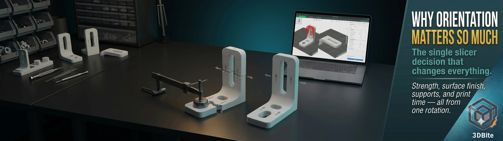
The same STL file, printed in two different orientations on the same printer with identical settings, can produce two parts with meaningfully different strength, different surface finish, different print time, and a different chance of the print actually completing successfully. No other single decision in the slicer has this much leverage over the outcome, and it is made before any of the settings that usually get the attention — before layer height, before infill, before speed. Understanding why orientation matters this much requires understanding one specific fact about how FDM printing actually builds an object: it is not building a solid piece of plastic. It is stacking and bonding a large number of individually printed threads, and the bond between those threads is never as strong as the threads themselves.
The core physics: FDM parts are anisotropic
Anisotropic means a material’s properties differ depending on which direction you measure them in. Wood is the everyday example — strong along the grain, weak across it, and everyone who has ever tried to split a log intuitively understands the difference. FDM printed parts are anisotropic for the same underlying reason: they are built from continuous strands of plastic laid down in a specific direction, layer after layer, and the strand itself is a fundamentally different structure from the bond between one strand and the one printed above it.
Within a single layer, the plastic is continuous — the nozzle extrudes one uninterrupted thread of molten material along the toolpath, and that thread is as strong as the base polymer’s own tensile properties allow. Between layers, the situation is different. Each new layer is deposited on top of a layer that has already begun cooling. The two layers fuse through partial remelting and diffusion at their interface, but this bond is never as strong as the material itself — some of the polymer chain entanglement that gives plastic its strength happens within a continuous extrusion and does not fully re-establish across a layer boundary that has already started to solidify. This is why every serious guide to FDM strength states the same fact in different words: FDM parts are weakest between layers and strongest along the direction the filament was actually extruded.
Orientation is the decision that determines which of these two very different strength profiles a given feature of your part actually relies on. Get it right, and the load a part experiences travels through the strong, continuous plastic. Get it wrong, and the same load is resisted only by the weaker layer-to-layer bond — and the part fails at a stress level that the material itself could have handled easily if the print had simply been rotated before slicing.
Working out which orientation actually helps a specific part
The practical question is always: where will this part experience force, and in what direction? Once you know that, the orientation principle is straightforward, even though different guides phrase it in ways that sound contradictory at first glance. The one thing to avoid is a part where the main tension or bending force runs through the stack of layers rather than along them — that is the orientation that relies entirely on the weak interlayer bond and is most likely to delaminate.
A bracket that bolts to a wall and holds a shelf, where the load pulls the bracket downward and puts the mounting point in shear, should be printed flat on the bed with the bolt holes running through the plane of the layers rather than stacked vertically through them. This keeps the load-bearing cross-section as continuous extruded plastic rather than relying on the weaker bond between layers to hold the bolt hole’s structure together.
A snap-fit clip that needs to flex repeatedly without cracking should have its flex axis running within a layer’s plane rather than across the stack. Flexing across layer boundaries repeatedly is exactly the fatigue scenario that causes printed snap-fits to crack at the hinge point after a surprisingly small number of cycles — the weak interlayer bond is being asked to absorb repeated bending stress that it was never going to handle well.
A part under tension along its length — a hook, a hanging bracket, anything being pulled lengthwise — should be printed so its length lies in the build plate’s plane rather than standing vertically. Standing it up means every layer boundary along that length is a potential failure point directly in the path of the pulling force. Lying it down means the pull travels through continuous extruded plastic along the part’s length, with the (much weaker) layer boundaries running crossways to the force rather than directly in its path.
This is the single rule underneath all of the specific advice: identify the direction the part will be stressed in actual use, and orient the print so that direction runs through as much continuous extruded plastic as possible, with as few layer boundaries directly in the load path as the geometry allows.
Overhangs and support: the second major consequence of orientation
Beyond strength, orientation is the primary lever for controlling how much of a model needs support material. Every surface that overhangs more than roughly 45-60 degrees from vertical — the exact threshold depends on the printer, the material, and the cooling settings — needs either support underneath it or a printed bridge spanning across it, and both come with a cost.
Support material adds print time, adds filament waste, and leaves visible marks where it contacted the model — surface texture that requires sanding or scraping to remove, and that never quite matches the surrounding finish even after cleanup. Reorienting a model before slicing so its natural overhangs point toward the build plate rather than out into open air can eliminate large sections of support entirely. A model designed with a 30-degree overhang on one face might need extensive support in its default orientation but need almost none once rotated so that face is closer to vertical or so the overhang faces downward onto the plate directly rather than out into unsupported space.
This is directly relevant to the multi-part printing workflow covered in the multi-part printing post. One of the underappreciated advantages of splitting a model into separate colour parts is that each part can then be oriented independently for its own best printing angle, rather than the whole assembly being constrained to a single compromise orientation. A boot section can print sole-down for a perfect flat surface. A hat section can print brim-down so its overhangs face the plate rather than open air. Neither of those individually optimal orientations would be available if the whole figure had to print as one AMS job in a single fixed position.
Surface finish and dimensional accuracy
The surface facing upward during printing (away from the build plate, away from any support) generally receives the smoothest finish, because it is the surface the nozzle deposits onto directly without any obstruction. The surface facing the build plate gets the flattest and most dimensionally precise finish, because it is constrained by the flat plate itself rather than by the printer’s own positioning accuracy. Any surface that required support will show the texture of the support contact points once removed, regardless of how carefully the support was cleaned off.
For a display piece or figurine, the practical implication is to orient the model so the face that will be seen most — the front of a figure, the top of a logo — is the upward-facing surface during printing, even if this is not the fastest or most support-efficient orientation. Accepting a longer print time or additional support in exchange for the best surface on the face that actually matters is frequently the right trade to make, and it is a trade that only becomes visible once you are thinking about orientation deliberately rather than accepting whatever the slicer defaults to.
Dimensional accuracy also differs by axis. XY dimensions — measured within a single layer — are generally more accurate than Z dimensions, which accumulate the small variances of each individual layer’s height across the full stack. For a part with a critical tolerance in one specific dimension — a hole that needs to accept a specific bolt, a slot that needs to fit another component precisely — orienting so that critical dimension lies in the XY plane rather than the Z axis produces a more consistently accurate result.
Print time: often the biggest practical difference nobody accounts for
Every layer takes a broadly similar amount of time to print regardless of its area, within reason — the nozzle has to trace the perimeter and fill the infill for that layer’s cross-section before moving up. This means a tall, narrow orientation with many thin layers stacked high takes considerably longer than the same model rotated to lie flatter, with fewer, larger layers. A part that takes three hours standing upright might take one hour lying flat, purely because the flat orientation requires a third as many layer changes to reach the same total height.
This is not a reason to always print flat — the trade-offs discussed above (strength, surface finish, support requirements) frequently override the time saving, and a faster orientation that introduces a large overhang requiring extensive support may end up taking longer overall once the support printing time is added back in. But it is worth checking the estimated print time for a couple of candidate orientations before committing, particularly for large or batch prints where the time difference compounds significantly.
Print reliability: the orientation that keeps the part on the plate
Beyond strength and finish, orientation determines whether the print survives to completion at all. A tall, narrow model with a small footprint on the build plate is more prone to wobbling during fast toolhead movements, and in the worst case can detach from the plate entirely partway through a long print. A top-heavy shape balanced on a small base is at risk of tipping. Reorienting to give the part a wider, more stable base — even at the cost of a less optimal finish on the visible face — is frequently the difference between a print that completes and one that fails at hour six of an eight-hour job.
This connects directly to the ringing and vibration discussion in the high-speed printing post. A tall, narrow orientation amplifies the physical consequences of high acceleration and vibration precisely because there is more unsupported height for the toolhead’s movement to shake. Reducing speed for tall, narrow prints — many experienced users create a dedicated printer profile that cuts speed by 20-30% specifically for this geometry — combines with orientation choice to produce more reliable results on exactly the prints that are most vulnerable to both problems simultaneously.
Material changes how much orientation matters
The strength penalty of a poorly chosen orientation is not identical across every material. PLA shows a fairly pronounced difference between well-oriented and poorly-oriented prints because its layer adhesion, while adequate, is not exceptional. PETG generally produces better layer bonding than PLA, which means the strength gap between a good and bad orientation is somewhat less dramatic — though still present and still worth planning for on any genuinely load-bearing part. Materials prone to warping or interlayer separation, ABS being the clearest example, can show a more pronounced anisotropic weakness, making orientation planning even more important for functional ABS parts than for the equivalent PLA print.
This is a reason to think about orientation specifically rather than applying a single rule of thumb across every material and project. A decorative PLA figurine where nothing structural is at stake benefits from orientation choices focused on surface finish and support minimisation. A functional PETG bracket carrying real load benefits most from orientation choices that protect the load path through continuous plastic. The same model can reasonably be oriented differently depending on which material it is being printed in and what it is actually for.
The practical checklist
Before slicing anything that matters — functional or decorative — work through these in order: identify how the part will actually be loaded in use and orient so that load travels through continuous plastic rather than across layer interfaces. Check for overhangs that the current orientation creates and consider whether rotating reduces or eliminates the support they require. Check which face will be most visible or dimensionally critical and orient that face upward or against the build plate as appropriate. Check the part’s footprint and stability on the plate at the chosen orientation, particularly for tall or top-heavy geometry. Only once those are settled is it worth comparing estimated print time between the remaining reasonable candidates.
None of this requires redesigning the model. It requires rotating it in the slicer before hitting slice, and thinking for thirty seconds about how the finished object will actually be used. That thirty seconds is consistently the highest-leverage thing you can do to a print before it starts, and it costs nothing beyond the attention.