Carbon fibre composite filament gets most of the attention in the engineering materials discussion. It is the name people recognise and the one that appears in more product listings. Glass-filled filament is quieter, cheaper, less photogenic — and in a specific set of applications, the better engineering choice. Understanding when that is true requires knowing what the glass actually does to the polymer it is added to, and how that differs from what carbon fibre does. They are not interchangeable. They are different tools for different problems, and choosing between them on the basis of which sounds more impressive is how you end up with the wrong part failing in an avoidable way.
What glass-filled filament actually is
Glass-filled filament — labelled GF, or occasionally GFR for glass-fibre reinforced — is a composite material made by mixing short chopped glass fibres into a base polymer during manufacturing. The fibres are typically 50 to 200 microns long, randomly distributed throughout the polymer matrix. Loading percentages vary by product: 10% GF is a light reinforcement that modifies handling more than properties, while 30% GF — the most common designation for serious engineering grades — produces meaningful gains in stiffness and heat resistance. Products above 30% GF exist for specialist applications but become increasingly difficult to extrude reliably on desktop hardware.
The same glass reinforcement approach is applied to a range of base polymers. PETG-GF is the most accessible entry point — familiar print characteristics with enhanced properties and no enclosure requirement. PA6-GF and PA12-GF (nylon with glass fibre) are the most widely used engineering grades and the materials that most directly compete with injection-moulded glass-filled nylon in traditional manufacturing. ABS-GF exists for applications where ABS’s base properties are needed alongside reinforcement. At the industrial end, PEEK-GF is available from specialist suppliers for demanding aerospace and medical applications — a material that costs considerably more than ordinary filament and requires hardware capable of 400°C+ nozzle temperatures.
What the glass fibres actually do
Glass is harder and stiffer than the polymer it is added to. When the polymer is stressed — bent, pulled, or compressed — the load transfers partly to the dispersed glass fibres, which resist deformation more than the polymer matrix alone would. The practical result is a stiffer part, better resistance to deformation under sustained load, and improved dimensional stability under heat.
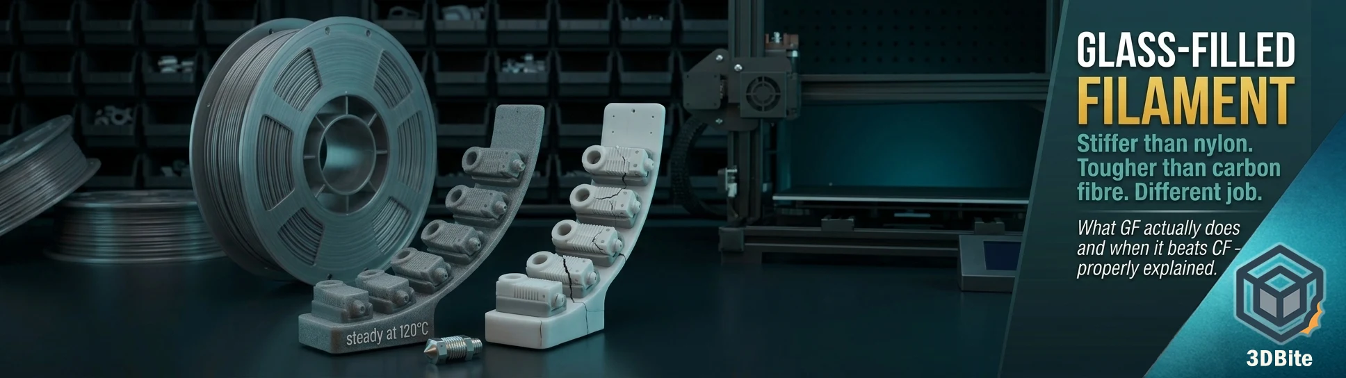
That last point is the one that distinguishes glass-filled from carbon-fibre-filled in a way that matters for specific applications. Glass-filled nylon maintains its shape at elevated temperatures better than both unfilled nylon and carbon-fibre-filled nylon. The glass fibres act as a thermal reinforcement as well as a mechanical one, reducing the degree to which the polymer softens and flows at elevated temperatures. A glass-filled nylon part can typically handle sustained temperatures 15-30°C higher than an equivalent carbon-fibre-filled part before beginning to deform under load. For anything near a heat source — automotive underbonnet applications, brackets in a workshop near a heat gun or oven, components near the heated bed of another printer — this distinction is the deciding factor rather than an academic distinction.
Glass-filled nylon is up to 80% stiffer than unfilled nylon according to published test data, with improved resistance to warping under heat and load. Those are significant gains from the reinforcement. What glass reinforcement does not do is produce the same level of stiffness that carbon fibre achieves. This is the most important distinction between the two composites: GF improves stiffness considerably over the base polymer, while CF typically improves it further still, and CF parts have the characteristic rigidity that makes them feel like machined components. Glass-filled parts are stiffer than the base polymer, but they still have some flex. That flex is the other side of the property that is glass-filled’s specific advantage.
Glass versus carbon fibre: the actual comparison
These two composites are compared constantly and usually with the framing “which is stronger?” That question has no single answer because they fail differently and excel in different conditions. The real question is which property your specific application needs.
| Property | Glass fibre (GF) | Carbon fibre (CF) |
|---|---|---|
| Stiffness (Young’s modulus) | Significantly higher than base polymer | Higher than GF — more rigid |
| Impact toughness | Better — deforms before fracture, absorbs shock | Lower — more brittle under sudden impact |
| Thermal stability | Better — holds shape at higher sustained temperatures | Good but lower thermal ceiling |
| Fatigue / cyclic loading | Better — handles repeated flex without cracking | Can become brittle under sustained vibration |
| Abrasion resistance | Better in sliding contact applications | Lower in sliding/contact wear scenarios |
| Dimensional accuracy / warp resistance | Good | Better — less warping, tighter dimensional stability |
| Weight | Heavier than CF at equivalent loading | Lighter |
| Cost | Lower than CF at equivalent base polymer | Higher |
| Nozzle wear | Very high — hardened nozzle mandatory | Very high — hardened nozzle mandatory |
The practical decision reads like this: if your part needs to be as stiff as possible and dimensional accuracy is the priority — a structural bracket, a housing that cannot flex — carbon fibre is the correct choice. If your part will be impacted, dropped, exposed to vibration, subjected to sliding contact, or operating near a heat source — GF is the better choice. The two composites occupy different positions in the performance space rather than one simply being better than the other.
PETG-GF: the accessible starting point
For anyone on an A1 or A2L wanting to explore glass-filled printing without moving into the more demanding territory of nylon, PETG-GF is the natural entry point. The print profile is similar to standard PETG — nozzle temperature around 240-260°C, bed at 80-85°C, no enclosure required — with two changes. The hardened steel nozzle is non-negotiable. And print speed needs to come down by roughly 20-30% compared to a standard PETG run, because the glass fibres increase the melt viscosity and the filament itself is more brittle on the spool than unfilled PETG, with a risk of snapping at tight bend radii.
What PETG-GF produces over standard PETG: noticeably better stiffness, reduced creep under sustained load, and better dimensional stability at elevated temperatures. For parts that live in moderately warm environments — a workshop, a car interior in summer, near other heat-generating equipment — PETG-GF holds its shape where standard PETG might sag. It is not a substitute for nylon in demanding thermal environments, but it bridges the gap between standard PETG and engineering nylon in a more accessible printing package.
PA-GF: the full engineering case
Nylon-GF — PA6-GF and PA12-GF are the most common grades — is where the glass reinforcement argument is strongest. The combination of nylon’s inherent toughness, chemical resistance, and fatigue performance with the dimensional stability and thermal reinforcement of glass fibre produces a material that holds its position in injection-moulded glass-filled nylon applications across automotive, industrial, and consumer products. This is not an aspirational claim: glass-filled PA is literally the material specification for the brackets, housings, and functional components in an enormous proportion of manufactured products. Desktop FDM printing in PA-GF is making those material properties accessible at prototype and small-batch scale.
The print requirements step up from PETG-GF. Nozzle temperatures of 250-280°C depending on the specific grade, bed temperatures of 70-100°C, and an enclosure is strongly recommended — both for the layer bonding quality that nylon printing requires and for the dimensional stability during printing that prevents stress from building into warped layers. Drying is not optional: PA-GF absorbs moisture more aggressively than most filaments, and wet PA-GF prints exhibit the blistering, stringing, and weak layer adhesion that moisture causes at these temperatures in a more dramatic way than damp PLA or PETG. Dry thoroughly before printing — twelve hours at 70-80°C — and use a drybox during long print runs.
A 0.6mm nozzle rather than 0.4mm is the community consensus for GF composites specifically, for the same reason it applies to CF composites: the larger bore reduces clogging risk from the glass fibres, reduces the contact pressure that causes nozzle wear, and generally produces more reliable extrusion through a material that is asking more of the hotend than standard polymers do. The surface finish is coarser at 0.6mm than at 0.4mm, but GF parts are almost never chosen for their surface finish. They are chosen for their mechanical properties, which the larger nozzle does not compromise.
The nozzle warning: same as CF, stated clearly
This bears stating separately rather than buried in the settings table because the failure mode for getting this wrong is invisible until it has already happened. Glass is harder than brass. Glass-filled filament through a brass nozzle erodes the bore progressively. The dimensional accuracy of the extrusion degrades without obvious symptoms until the bore has widened enough to produce visible quality loss — blobs, inconsistent wall width, rougher surface finish — and by that point the nozzle is damaged and needs replacing. The abrasive filament guide covers this mechanism in full in the dedicated post. The short version for glass-filled specifically: fit a hardened steel nozzle before the first spool goes on. Do not treat this as optional because you are “just trying it.” The first print with GF filament in a brass nozzle begins the wear immediately.
What glass-filled filament is actually good for
The applications where glass-filled earns its place over standard polymers and over carbon-fibre composites are fairly specific, and being specific about them is more useful than a general “stiffer and stronger” framing.
Parts operating near heat sources are the clearest case. A bracket that will sit near an engine, a tool holder near a heat lamp, a component near the electronics of another machine that generates sustained warmth — GF’s thermal reinforcement holds shape where CF-filled and unfilled variants would begin to deform. This is the application where the GF choice is least controversial and most clearly validated by the injection-moulded parts industry that has been making exactly this selection for decades.
Vibration-exposed applications are the second clear case. Drone frames, RC vehicle chassis, machine brackets near motors, anything that will experience sustained cyclical loading — glass-filled handles fatigue better than carbon-fibre-filled because the slightly more ductile GF composite absorbs and dissipates vibration energy rather than accumulating it as stress. Carbon-fibre-filled parts in vibration-heavy environments can develop micro-cracks at stress concentrations and eventually fracture in a way that GF’s toughness resists. For a motor mount on a printer, a bracket near a vibrating tool, or any mechanical component with an AC motor nearby, GF is a better specification than CF.
Sliding contact applications are worth naming explicitly because they come up in specific print projects. Anything that rides against another surface — a linear rail guide, a slide mechanism, a bushing — benefits from GF’s better abrasion resistance in contact wear scenarios. CF in sliding contact applications tends to wear relatively quickly. GF holds up better when the part itself is the wear surface. This is a specific consideration for printer modifications, jigs and fixtures, and any functional mechanism with moving parts in contact.
Parts that will be impacted or dropped round out the practical list. A protective housing, a case, a cover for a piece of equipment that might be handled roughly — GF’s toughness advantage over CF means it deforms slightly rather than fracturing on impact. A dropped CF housing may crack or shatter at the layer lines. The equivalent GF housing absorbs the impact energy and survives it. If the application involves any expectation of physical shock, glass-filled is the correct composite choice.
Where to find it
PETG-GF options have expanded significantly in recent years and most major filament brands offer at least one variant. Polymaker’s PolyMide PA6-GF is widely available and well-documented, a good entry point for PA-GF printing. Spectrum produces PA12-GF. 3DXTech’s FibreX range covers PA6-GF, PA12-GF, ABS-GF, and the more exotic PEEK-GF for anyone whose application justifies the cost. Bambu Lab produces a PA6-GF that works with the P series and H series machines whose enclosed chambers and higher-temperature hotends are better suited to nylon-based engineering materials than the open-frame A-series. For PETG-GF specifically, the options are broad enough that a search of any major filament retailer will return multiple choices at accessible prices.
The pricing gap between GF and CF filaments at equivalent base polymers is real and meaningful at hobbyist scales. PETG-CF and PETG-GF from comparable brands typically sit within a few pounds of each other per kilogram, but the premium PA and PEEK grades can differ more significantly. For most applications where you are comparing the two, the decision should be driven by the application requirements first and cost second. The wrong material chosen because it was slightly cheaper is not a saving when the part fails or performs below the requirement.
Summary
Glass-filled filament is a composite that improves stiffness, thermal stability, and dimensional stability over the base polymer, with better impact toughness, fatigue resistance, and abrasion performance than carbon-fibre-filled equivalents at the cost of marginally lower stiffness ceiling. It is not CF with better marketing. It is a different material that is better suited to different problems. The hardened steel nozzle requirement, slower print speeds, and for nylon grades the enclosure and drying requirements are real constraints that make it more demanding than standard polymers. The payoff is parts that perform in conditions where standard filaments would deform, crack, or wear out. For the right application, it is the right material.