Functional prints rely on more than just strong filament and good layer adhesion. Infill acts as the internal framework that dictates how a part deals with real loads, impact and long-term stress. The pattern defines how forces travel through the part, and the density controls how much internal support is available to carry those forces. Choosing the right combination lets you tune strength, weight and print time with more precision than most people expect. A well matched infill strategy can reinforce stressed areas, lighten sections that do not need extra material and reduce print time without sacrificing reliability.
This guide focuses on practical recommendations that work well on Bambu printers.
1. Start with Walls, Not Infill
Before tuning infill, decide how many perimeters the part needs. Walls typically contribute more to strength than infill.
- Light functional parts: 3 walls
- Structural parts: 4–6 walls
- Load-bearing features: 5+ walls and 30–60 percent infill
2. Choose an Infill Based on Load Type
Different patterns behave differently under stress. Pick one that aligns with how the part is used. Here’s non-exhaustive list:
Rectilinear: The use of a single-direction line per layer significantly shortens the print path, greatly improving print speed
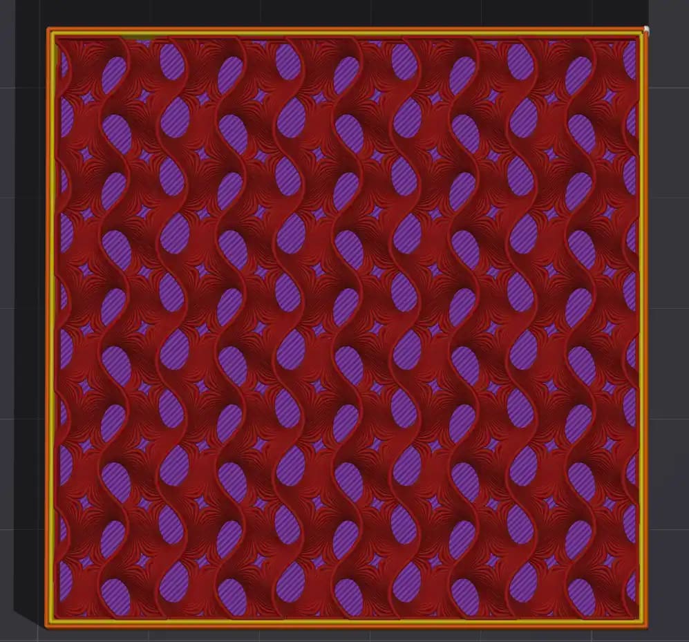
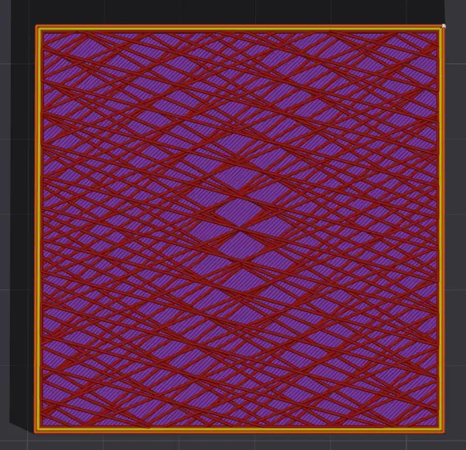
Gyroid: Best all-round choice. This TPMS-based spiral infill provides strong multidirectional support and prints quickly thanks to its non-intersecting layer paths. Its complexity increases slicing time and G-code size, and at higher densities or speeds it can introduce noticeable vibration.
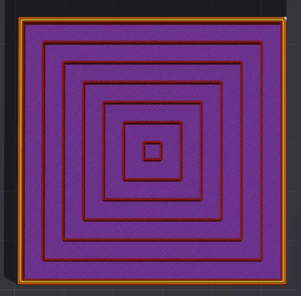
Concentric: A sparse infill pattern that’s good for aestetic effect
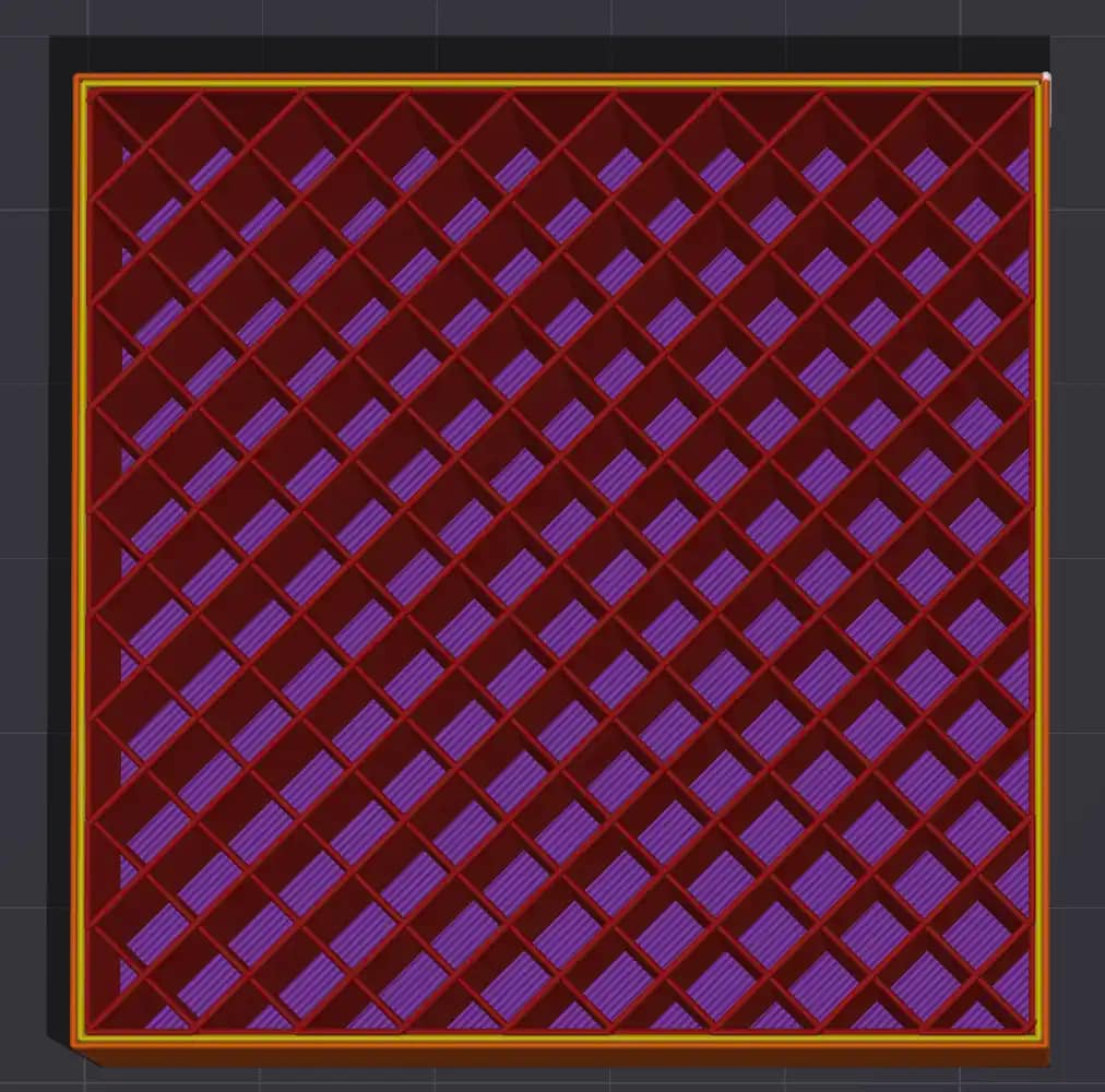
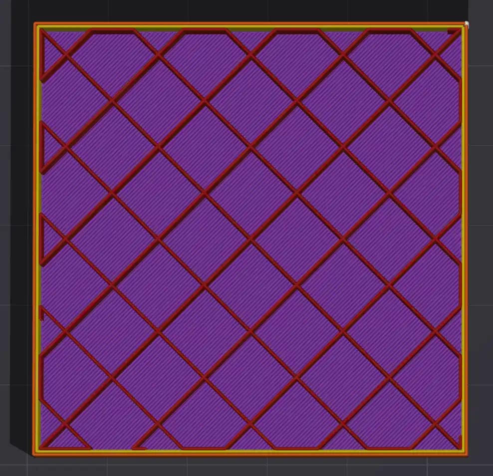
Grid: Grid infill uses two perpendicular sets of parallel lines to form a simple, fast crosshatch structure. Its overlapping intersections can cause minor material buildup, and at higher speeds the nozzle may scrape or generate odd noises as it passes over these points.
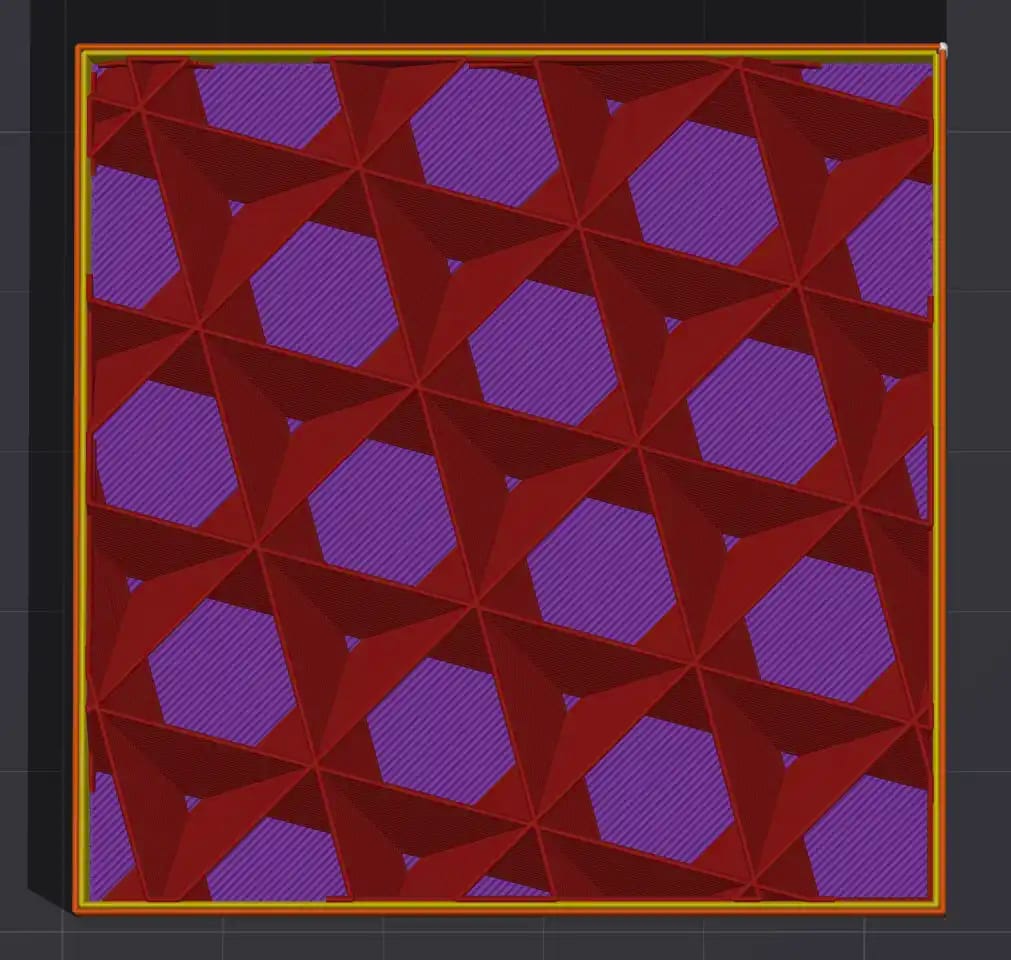
Triangle / Cubic: These patterns offer a consistent spread of strength, giving steady mechanical performance across the X, Y, and Z axes. It’s a good choice when you need a balance of structural integrity and printing efficiency.
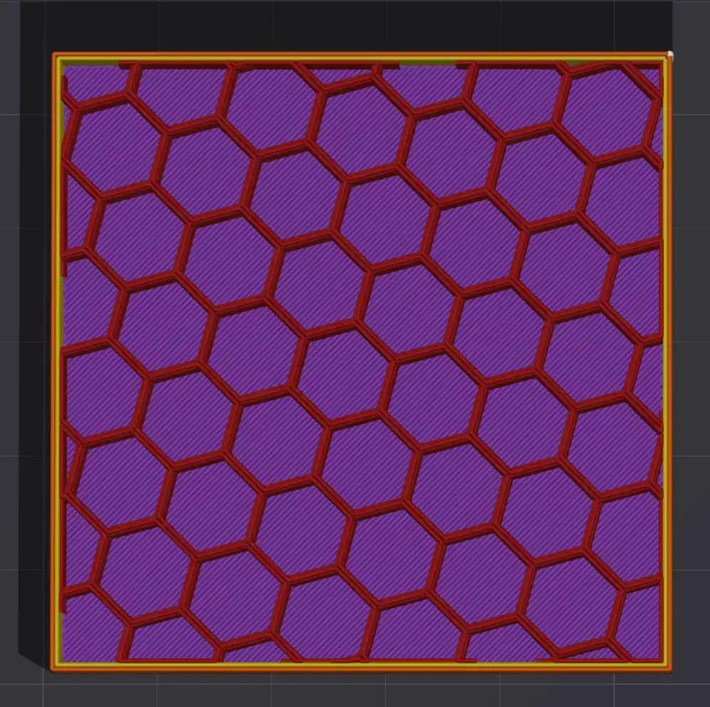
Honeycomb: This infill delivers a clear boost to rigidity and impact resistance. The trade-off is a more intricate toolpath, which slows slicing and adds to the total print time.
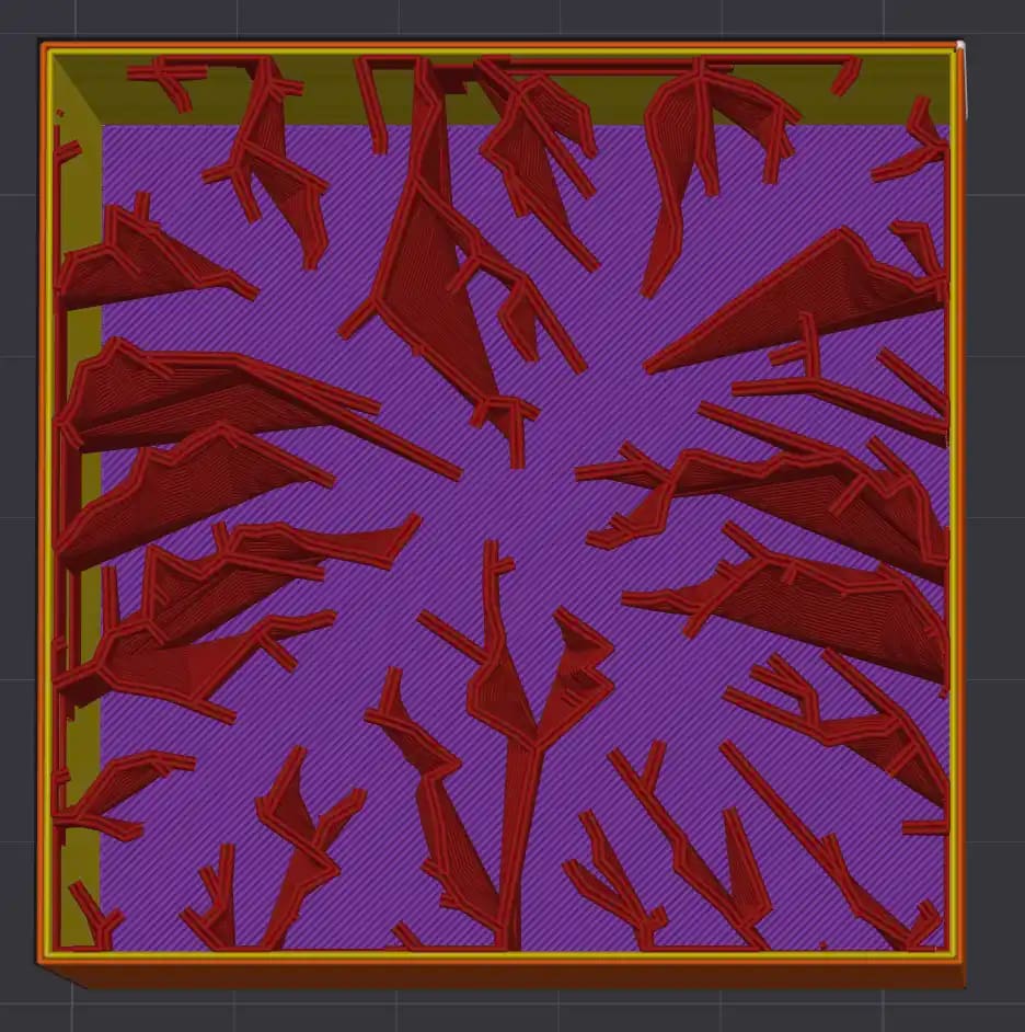
Lightning: Lightning Infill is a serrated minimal pattern used only in the layer beneath the top surface, giving just enough support where it’s needed. It cuts print time and material use dramatically, making it ideal for decorative or aesthetic models that don’t need structural strength.
Zig zag: This pattern keeps the nozzle moving in a steady rhythm, avoiding retractions and hesitations, which gives you faster print times. Its structural strength is modest, so it’s best reserved for parts that don’t need to carry much load.
3. Match Density to Use Case
Infill density is a practical way to tune the strength, weight and print time of any 3D printed part. Low infill works well for cosmetic prints, prototypes and models that do not carry load, since the printer can move quickly and use less material while still producing a clean outer shell. Once a part needs to handle real forces, such as mounting brackets, hinges or tool holders, the internal structure needs to do more work. Mid-range densities give the infill enough presence to distribute stress and reduce flex without adding unnecessary weight.
For parts that face repeated load, vibration or impact, higher infill becomes a functional requirement. In these cases the goal is not simply to make the part heavy. It is to ensure the internal structure supports the outer walls and carries forces through predictable paths. Different materials behave differently at the same percentage, so PLA at forty percent is not identical to PETG at forty percent. Matching infill density to the use case is ultimately about giving each part the internal support it needs to perform reliably without wasting print time or filament.
| Use Case | Infill Percentage |
|---|---|
| Cosmetic only | 0–10 percent |
| Light functional | 12–20 percent |
| Brackets and tools | 25–40 percent |
| Load-bearing | 40–60 percent |
| Near-solid mechanical parts | 70–100 percent |
4. Consider Part Geometry
Part geometry has a direct impact on how you should approach infill. Thin or narrow prints benefit more from additional walls than from pouring material into the centre. The strength comes from the shell, so you can keep infill low without compromising performance. Wide, flat plates behave differently. They tend to warp or flex unless the internal structure gives them something to push against, so a higher infill percentage helps stabilise the entire footprint. Tall objects introduce another set of requirements. They need stiffness along the vertical axis, which is where patterns like Cubic or Gyroid perform well. Matching infill strategy to the geometry ensures the part stays stable, prints cleanly and performs the way you expect.
- Thin or narrow prints: More walls, lower infill
- Wide, flat plates: Higher infill to prevent warping
- Tall objects: Cubic or Gyroid for vertical stiffness
5. Support and Infill Interaction
When supports rely on infill beneath them, the internal structure becomes part of the support system. Patterns like Grid or Cubic Subdivision create predictable, flat contact points that prevent the support interface from sagging or drifting during the print. In these cases it helps to keep the infill density at or above twenty percent so the supports have a reliable foundation to anchor to. Too little density leaves gaps and uneven surfaces, which can lead to poor overhang quality or failed support structures. A stable infill pattern gives the whole support stack the consistency it needs to print cleanly.
If supports sit on infill, use Grid or Cubic Subdivision and keep infill density at or above 20 percent.
6. Use Modifier Volumes
Apply high-density zones where the part needs localized strength. Examples include bolt holes, tabs, or mounting faces.
7. When to Use 100 Percent Infill
Use solid infill when the part needs material you can physically work with, such as drilling, tapping or clamping under high compression. In these situations the tool or load needs continuous material so forces do not break through into voids. Solid infill also prevents threads or drilled holes from deforming because the internal structure is uniform. Outside of those cases, fully solid prints often add weight and print time without giving meaningful gains. A well tuned combination of strong walls and around forty to sixty percent infill spreads load efficiently and keeps the internal structure flexible enough to absorb stress rather than crack. This balance usually performs better in real use while keeping material costs and print times sensible.
8. Quick Reference
- General strength: Gyroid, 20–35 percent, 3–4 walls
- Brackets/arms: Triangles, 30–45 percent, 4–6 walls
- Impact-heavy parts: Honeycomb, 40–60 percent
- Fast prints: Lightning, 5–10 percent
- TPU: Gyroid or Cubic, 10–20 percent